Eureka AIR delivers breakthrough ideas for toughest innovation challenges, trusted by R&D personnel around the world.

Broadband communication system using point and shoot approach

Inactive Publication Date: 2006-03-28
ERICSSON INC
View PDF10 Cites 12 Cited by
  • Summary
  • Abstract
  • Description
  • Claims
  • Application Information

AI Technical Summary

Benefits of technology

[0009]The index signals are transmitted over a narrow band beam and the information signals are transmitted over a broadband beam from the satellite to a plurality of receivers. Each receiver continuously demodulates and decodes the narrow band index signal. The index signals are transmitted over a narrow band beam with the same bit rate as the information signals. The ground-based receivers continuously demodulate and decode the narrow band beam. The receiver, using address information contained in the index signal, locates and extracts data in the information signal intended for that receiver. When an address appears in the index signal that matches the receiver's address, the target receiver enables an onboard buffer to record or store a relevant portion of the information signal. B

Problems solved by technology

The use of multimedia broadband applications in the Ka band (30/20 GHz) for satellite communication systems raises the problem of dealing with very high-speed data transmission rates, especially in the forward link segment, from satellite to the user terminals, where a broad spectrum of data is accommodated in each carrier.
The main problem to overcome in a broadband communication system is how the user terminals or receivers can be made to demodulate and process the incoming high-speed data stream without requiring technology that is excessively sophistic

Method used


Image

  • Broadband communication system using point and shoot approach
  • Broadband communication system using point and shoot approach
  • Broadband communication system using point and shoot approach

Examples


Embodiment Construction

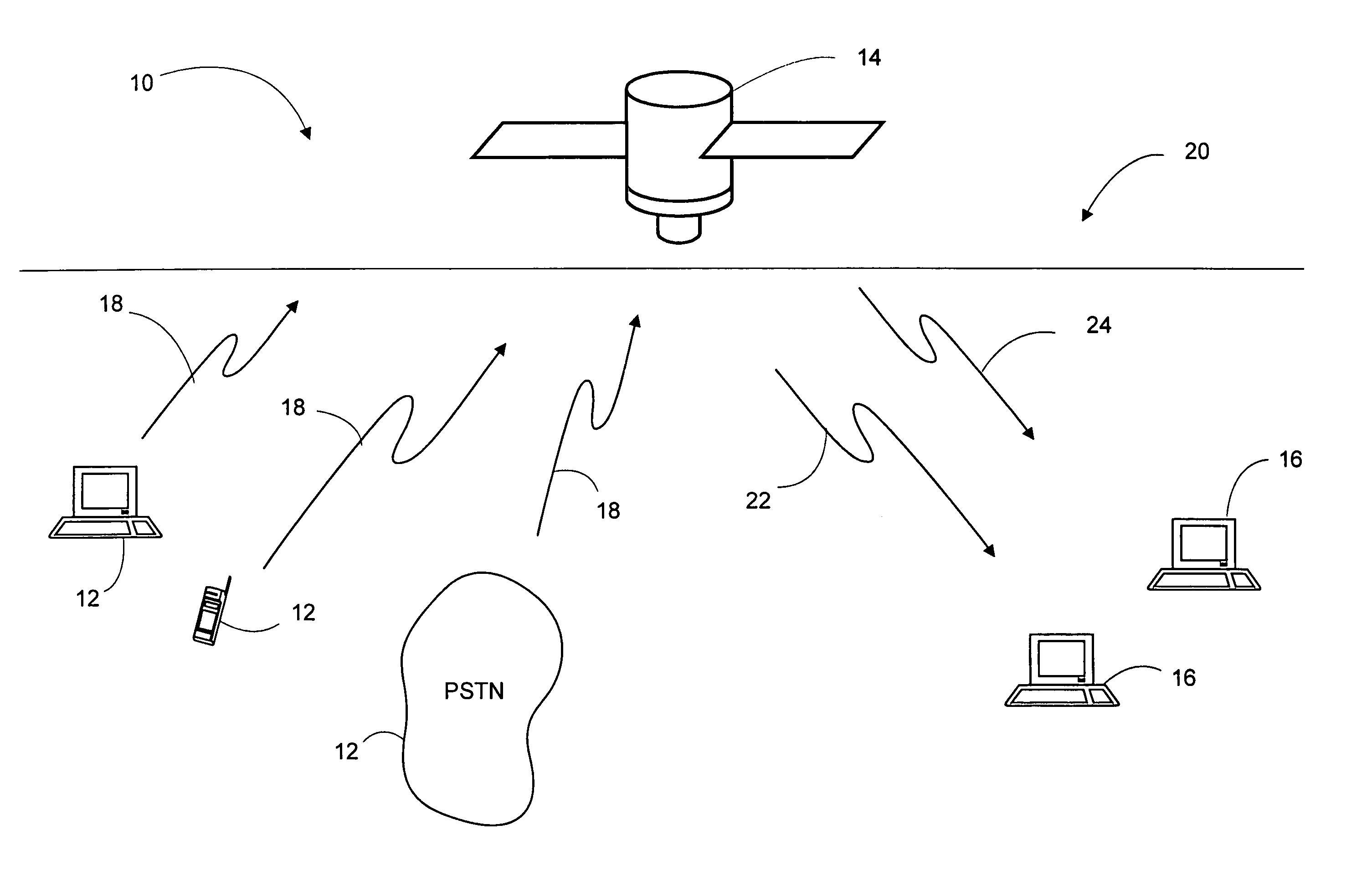
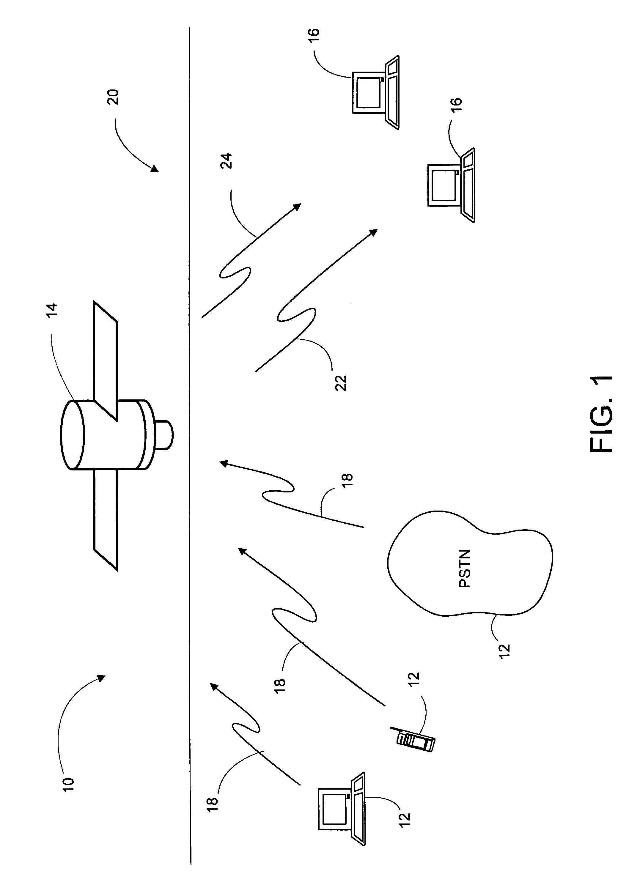
[0015]Shown in FIG. 1 is a functional schematic diagram that illustrates a broadband communication system generally indicated by the numeral 10. Communication system 10 comprises a plurality of ground-based transmitters 12, an orbiting satellite transceiver 14 and a plurality of ground-based user terminals or receivers 16. It should be appreciated that while the particular embodiment shown in FIG. 1 assumes that the transmitter 12 and receiver 16 are ground-based and that the transceiver 14 is spaced-based, in practice these network components could be stationed in a variety of configurations.

[0016]The ground-based transmitters 12 broadcast the information signal via uplink 18 to the transceiver 14. As shown in FIG. 1, the information signals 18 are received and re-transmitted by the orbiting satellite transceiver 14 via downlink or forward link 20 to a plurality of receivers. The downlink 20 may comprises a single carrier beam or a multi-carrier beam. In a conventional satellite co...


PUM


Abstract

A broadband communication network uses a point and shoot approach for data transmission. A broadband information signal is transmitted from a transmitting station to a receiving station. The information signal is divided into a series of data packets, each including addressing information and data intended for a particular receiver. The information signal is parsed to extract addressing information. The addressing information parsed from the information signal is used to construct a narrow band index signal. The narrow band index signal is transmitted, along with the broadband information signal, to a plurality of receiving stations. Each receiving station demodulates and decodes the narrow band index signal. The address information contained in the index field includes pointers to data packets in the information signal. Using the addressing information and pointers in the index signal, each receiving station can locate and extract data packets from the broadband information signal which are intended for that particular receiver. The data packets from the information signal are buffered to permit demodulation and decoding the particular packet(s) belong to that particular receiver at the same rate of the information signals.

Description

FIELD OF THE INVENTION[0001]The present invention relates to broadband communication networks, and more particularly to a multi-channel access scheme for providing shared access to a broadband carrier.BACKGROUND OF THE INVENTION[0002]The need for telecommunication networks capable of providing diverse and emerging communication services such as data, voice, and video motivated the development of broadband networks. Such networks offer users multimedia services, and the flexibility of accessing bandwidth on demand. Furthermore, there is increasing recognition of the benefits and advantages of using satellite transmission systems which will no doubt play a significant role in establishing a communications infrastructure for broadband communications.[0003]The use of multimedia broadband applications in the Ka band (30 / 20 GHz) for satellite communication systems raises the problem of dealing with very high-speed data transmission rates, especially in the forward link segment, from satel...

Claims


Application Information

Patent Timeline
IPC IPC(8): H04J1/10H04B7/185H04Q11/04
CPCH04B7/18523H04Q11/0478H04J2203/0037H04J2203/0019
Inventor REFAI, WAIL M.
Owner ERICSSON INC
Why Eureka
Eureka Blog
Learn More