Pressure sealer apparatus

a sealing device and pressure sealer technology, applied in the direction of mechanical control devices, instruments, process and machine control, etc., can solve the problems of inconvenient installation, muddled sealing mail, and inability to align paper that is not aligned with the conventional pressure sealer apparatus, so as to prevent system shutdown

Inactive Publication Date: 2006-03-28
PRINTMAIL SOLUTIONS
View PDF14 Cites 6 Cited by
  • Summary
  • Abstract
  • Description
  • Claims
  • Application Information

AI Technical Summary

Benefits of technology

[0008]Another object of this invention is to provide compact and lightweight pressure sealer apparatus.
[0009]A further object of this invention is to provide a pressure sealer apparatus that allows on-line connection with a printer, and can automatically control activation and deactivation of the printing task during the occurrences of paper jamming to prevent system shutdown.
[0010]A further object of this invention is to provide a pressure sealer apparatus that can meet the needs of print-on-demand and print-to-mail.

Problems solved by technology

Though there are several models of commercially available pressure sealer apparatus that may achieve the above objects, such conventional pressure sealer apparatus cannot align papers that are not aligned, such that the adhesion is not aligned with the margins of the neighboring folds.
As a result, the sealed mails may be of a muddled appearance because adhesion coated to the papers is not properly sealed with the margins of the neighboring folds.
Such large-sized pressure cylinder, at the same time, must be driven by a heavy-duty motor such that it is common for the conventional pressure sealer apparatus weighing over 100 kilograms and consisting of a relatively large size, which is not suitable to be equipped in a regular office space but at a designated location, such as a mailroom.
The large size and heavy weight of the conventional pressure sealer apparatus prevents the conventional pressure sealer apparatus from being connected to a laser printer for on-line operations.
Apparently, such a process cannot meet the needs of print-on-demand and print-to-mail.

Method used


Image

  • Pressure sealer apparatus
  • Pressure sealer apparatus
  • Pressure sealer apparatus

Examples


Embodiment Construction

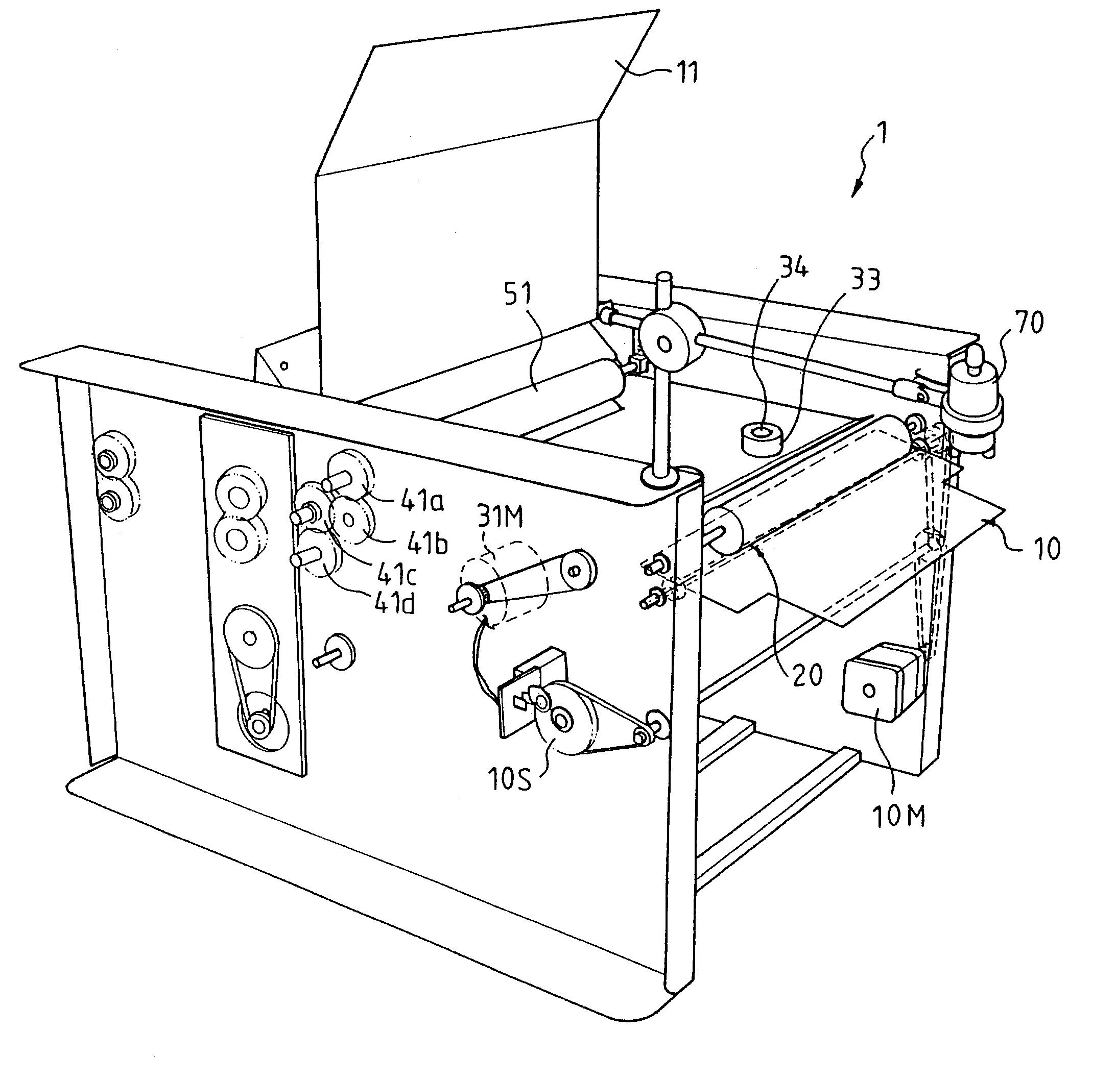
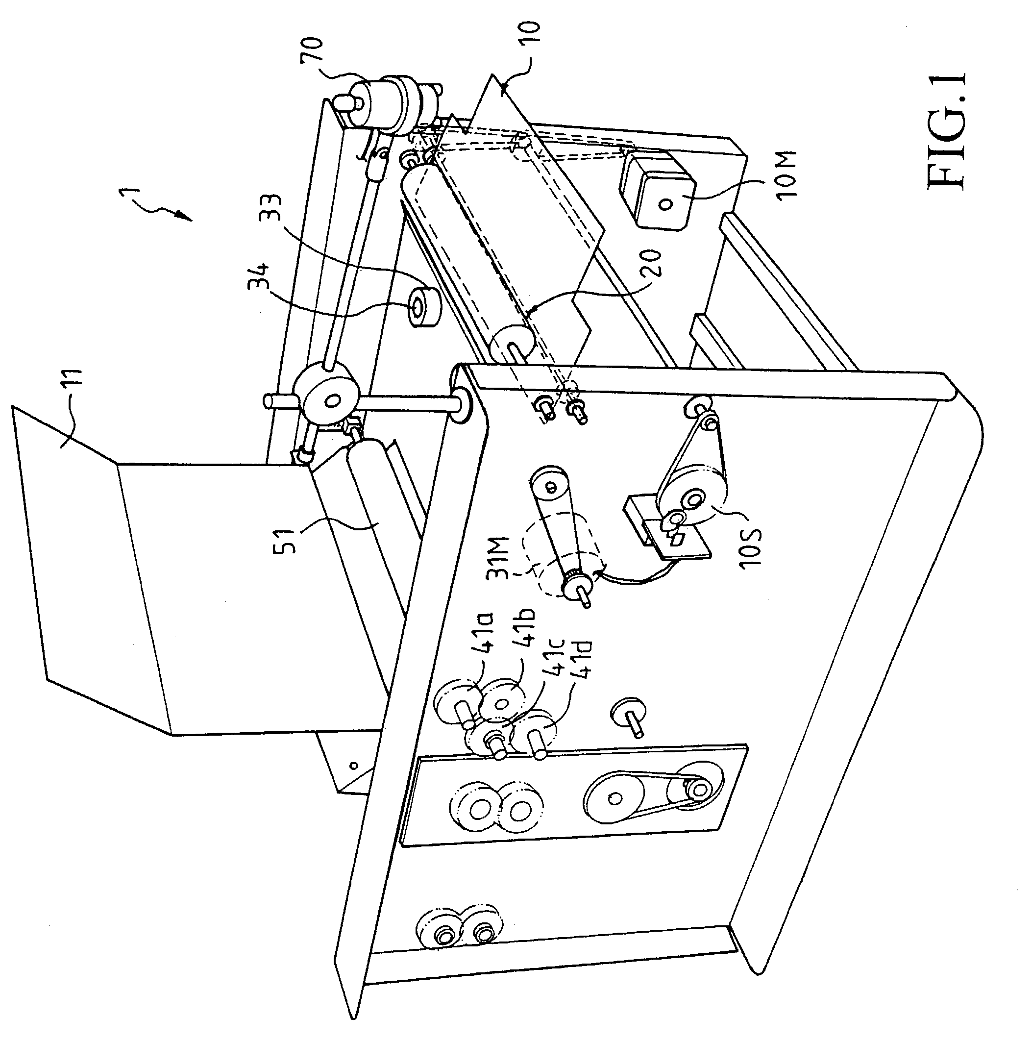
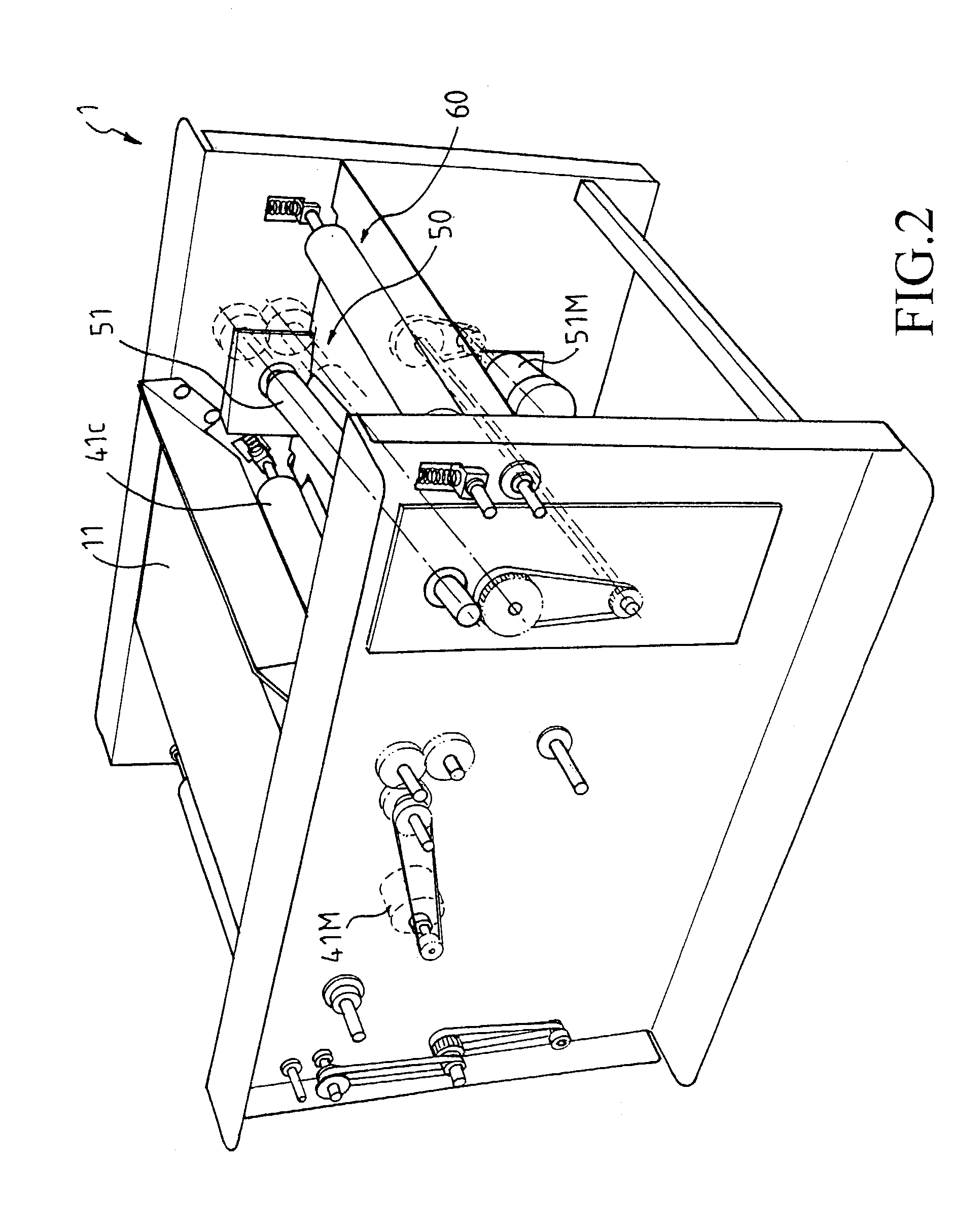
[0020]FIG. 1 illustrates a perspective view of a pressure sealer apparatus 1 according to this invention, wherein a lid 11 is in its open state. FIG. 2 is another perspective view showing a pressure sealer apparatus 1 according to this invention, wherein the lid 11 is in its closed state. The pressure sealer apparatus 1 in FIG. 2 is not provided with a manipulator; the functions of the manipulator will be described hereinafter. FIG. 3 is a cross-sectional, elevational view of the pressure sealer apparatus 1 according to this invention.

[0021]With reference to FIGS. 1 and 3, the pressure sealer apparatus 1 according to this invention comprises: a buffer 10, a paper entry 20, a paper alignment 30, a folding device 40, a presser 50, and an exit 60 that are sequentially provided from an upstream to a downstream of pressure sealer apparatus 1.

[0022]FIG. 4 illustrates the details of the buffer 10 and paper entry 20. FIG. 5 is a top plan view of the pressure sealer apparatus 1.

[0023]As show...


PUM

PropertyMeasurementUnit
adhesionaaaaaaaaaa
angleaaaaaaaaaa
sizeaaaaaaaaaa

Abstract

This invention provides a pressure sealer apparatus, for folding and sealing papers coated with adhesion at part of margins thereof into a smaller size, comprising: a buffer, controlled by a buffer motor and a buffer switch to move between an inactivated and an activated position; a paper entry provided at a downstream of the buffer; a paper alignment provided at a downstream of the paper entry, including an alignment roller set and a ball set, the ball set having a ball freely rotatable in a frame and suspended above the alignment roller set; a folding device provided at a downstream of the paper alignment; a presser provided at a downstream of the folding device, including a pressure cylinder situated to form an angle with respect to the alignment roller; and an exit provided at a downstream of the presser.

Description

CROSS-REFERENCES TO RELATED APPLICATIONS[0001]Not ApplicableSTATEMENT REGARDING FEDERALLY SPONSORED RESEARCH OR DEVELOPMENT[0002]Not ApplicableFIELD OF INVENTION[0003]This invention is related to a pressure sealer apparatus, particularly to one being compact and lightweight, and allowing on-line connection with a printer, such as a laser printer.BACKGROUND OF INVENTION[0004]Pressure sealer apparatus is commonly used for folding and sealing papers coated with adhesion at part of margins thereof into sealed mails of a smaller size. The pressure sealer apparatus may fold individual pieces of papers into two folds or three folds according to the users' needs and then apply forces to the folded paper, causing the pressure-sensitive adhesion coated to part of the margins of particular folds to seal with margins of neighboring folds, thereby forming a sealed mail that is ready to be dispatched.[0005]Though there are several models of commercially available pressure sealer apparatus that ma...

Claims


Application Information

Patent Timeline
Patent Type & Authority Patents(United States)
IPC IPC(8): B65H45/04B65H45/14B65H5/06B43M5/04B65H5/00B65H9/16
CPCB43M5/047B65H45/142B65H9/006Y10T156/1741
Inventor HSIEH, ELTON
Owner PRINTMAIL SOLUTIONS
Why Eureka
Try Eureka