
Tooth moving method and appliance

a tooth moving and appliance technology, applied in the field of tooth moving methods and tooth moving appliances, can solve the problems of narrowing or occupying space, disassembly of dentition, spoiling occlusion, etc., and achieves the effect of minimizing discomfort or pain, simple and less bulky tooth moving appliances, and convenient practi

Inactive Publication Date: 2006-03-28
TERAMOTO NOBUHISA
View PDF1 Cites 23 Cited by
  • Summary
  • Abstract
  • Description
  • Claims
  • Application Information

AI Technical Summary

Benefits of technology

[0013]In the light of the problems mentioned above, the present invention has been made. It is an object of the present invention to provide a tooth moving method and appliance that is simple and less bulky in itself, easy to be fitted on the teeth, less burdensome for the patients, and can cut down initial costs and running costs.
[0018]Accordingly, the present invention can provide the advantage of making the entire tooth moving appliance simple and less bulky in order to minimize an uncomfortable feeling or pain for the patient who fits the appliance in his / her teeth. This arrangement is to be compared with the conventional molar distal moving appliance having a configuration in which the inner wires and the tubes are fixed to the seamless bands, with their ends soldered to the seamless bands fitted on the teeth on the buccal side and on the lingual side, respectively. Further, according to the present invention, since the fitting of the tooth moving appliance onto the teeth can be practiced with ease at the location of the dental treatment, the components of the appliance can be produced in advance in large quantities. This can provide an additional advantage in that the manufacturing costs can be cut down drastically, differently from the conventional appliance that must be made painstakingly piece by piece, requiring experience and skill and taking lots of time and labor.
[0019]Moreover, according to the present invention, the connecting portions at which the inner wire and the tube are connected to their respective lingual buttons fixed to the teeth preserve such a certain degree of freedom of movement as to allow the inner wire and the tube to move toward the buccal side and the lingual side at the connecting portions. This can present comfort and fitness for the movement of each tooth of each individual patient, and, accordingly, can allow the teeth to always be biased in the direction for the teeth to be apart from each other, without complicated and precise adjustments and the like. This can provide the further advantage of providing enhanced dental treatment efficiency.

Problems solved by technology

When a primary dentition is missed early, the teeth on both sides thereof move into the missing tooth space, resulting in narrowing or occupying of the space when an incoming permanent tooth arrives.
As a result, the incoming permanent tooth is hindered from arriving (growing) at the right place, which causes disarrangement of the dentition.
This problem not only spoils the occlusion, but also adversely affects the facial appearance.
However, because of the configuration requiring that the inner wires and the tubes are firmly fixed to both seamless bands by soldering their ends to the buccal side of the seamless bands and on the lingual side of the same, this conventional type of molar distal moving appliance has the problem of taking much space in the mouth.
Thus, a patient who fits the appliance on the teeth becomes uncomfortable or experiences pain.
Further, since the seamless bands must be accurately designed and made to fit onto each tooth of each individual patient, it is infeasible to make a stock production.
For this reason, the conventional molar distal moving appliance must be made painstakingly piece by piece, requiring experience and skill and taking lots of time and labor, thus leading to the disadvantage of increased manufacturing costs.
In addition, the conventional molar distal moving appliance requires a high level of soldering technique for soldering the ends of the inner wires and tubes to the seamless bands, and also requires an expensive soldering device therefor.
Thus, the conventional appliance involves increasing initial costs and running costs.
Moreover, since the ends of the inner wires and tubes are firmly soldered to the seamless bands fitted on the teeth, a moving direction of the seamless bands is limited to the direction for the inner wires and the tubes to be slid.
This causes a problem in that when the conventional molar distal moving appliance is used, with its seamless bands fitted on the related teeth, a complicated and precise adjustment must be repeatedly made.
Consequently, the moving direction of the seamless bands is limited to the direction for the inner wires and the tubes to be slid.
This causes a problem in that it is almost impossible to move an obliquely arriving (growing) tooth by using the conventional molar distal moving appliance.
Further, the conventional molar distal moving appliance has a fatal problem in that there is a possibility that the seamless bands themselves cannot be fitted onto the obliquely arriving teeth, depending on the degree of inclination of the tooth and the degree of growth of the tooth.

Method used


Image

  • Tooth moving method and appliance
  • Tooth moving method and appliance
  • Tooth moving method and appliance

Examples


Embodiment Construction

[0037]In the following explanation, certain preferred embodiments of the present invention will be described with reference to the accompanying drawings.

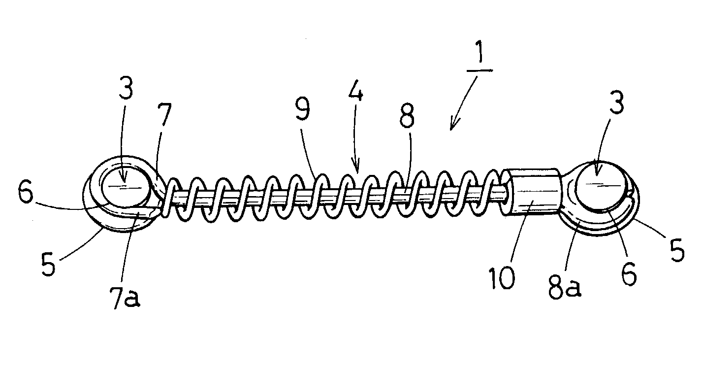
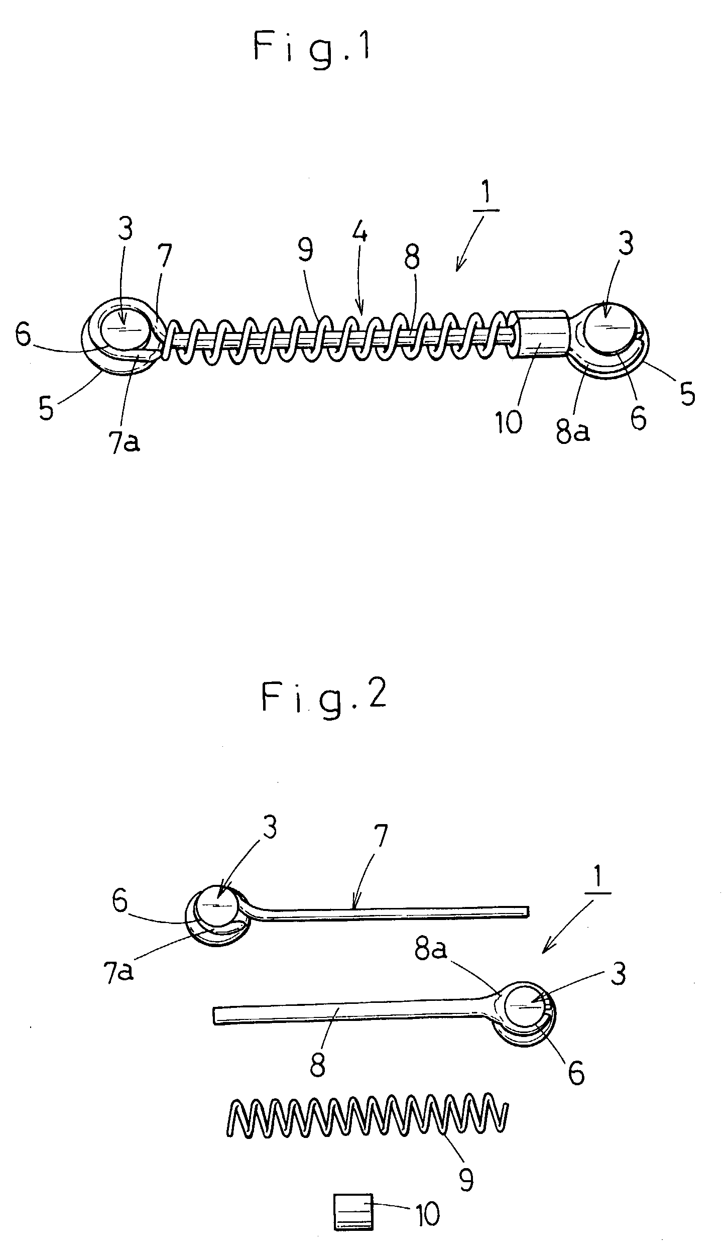
[0038]A tooth moving appliance 1 comprises two lingual buttons 3, 3 to be fixed to two teeth 2, 2 for spreading out the space between the teeth, or for correcting the dentition between the teeth, and a space-spreading biasing means (biasing device) 4 mounted between the two lingual buttons 3, 3, as illustrated in FIG. 12.

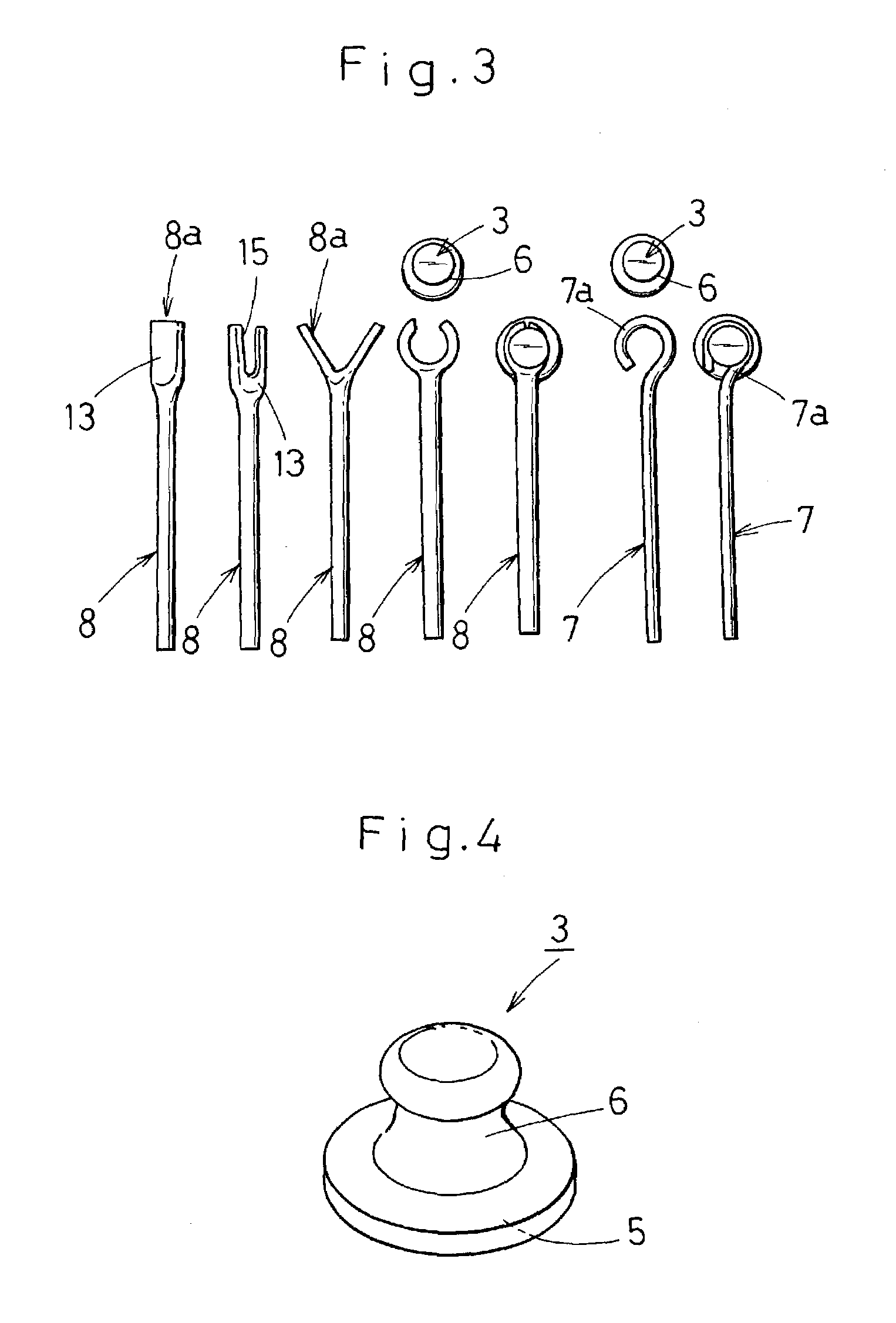
[0039]The lingual buttons 3 are formed of rust-resistant metal such as stainless steel. Each lingual button 3 is formed to have in the bottom a stick-on surface 5 to be stuck on a tooth surface 2a of the tooth 2, and a neck 6 constricted at a portion thereof above the stick-on surface 5, as shown in FIG. 4. As shown in FIG. 4, the neck 6 has wider end portions and a narrower (constricted) middle portion.

[0040]The space-spreading biasing means (biasing device) 4 comprises an inner wire 7 to be pivotally connected to ...


PUM


Abstract

A tooth moving method and appliance for securing a space for an incoming permanent tooth to arrive includes two lingual buttons to be fixed to two teeth, respectively, to spread out a space therebetween or correct a dentition therebetween. An inner wire is pivotally connected to a first lingual button at an end thereof, and a tube is loosely fitted onto the inner wire and pivotally connected to the other lingual button at an end thereof. An open coil is loosely fitted onto the tube, and a split stop is provided for adjusting the tensile force of the open coil. Thus the tensile force of the open coil is adjusted by the split stop to move at least either of the two teeth, so as to spread out the space therebetween to a desired extent.

Description

BACKGROUND OF THE INVENTION[0001]1. Field of the Invention[0002]The present invention relates to a tooth moving method and to a tooth moving appliance in an orthodontic clinic and the like.[0003]2. Prior Art of the Invention[0004]When a primary dentition is missed early, the teeth on both sides thereof move into the missing tooth space, resulting in narrowing or occupying of the space when an incoming permanent tooth arrives. As a result, the incoming permanent tooth is hindered from arriving (growing) at the right place, which causes disarrangement of the dentition. This problem not only spoils the occlusion, but also adversely affects the facial appearance.[0005]To avoid this problem, when a primary dentition is missed early, a method using a molar distal moving appliance (stationary type), which is generally called “GMD (Greenfield Molar Distalizar), is generally used to secure the space to allow the incoming permanent tooth to arrive.[0006]This known molar distal moving applianc...

Claims


Application Information

Patent Timeline
IPC IPC(8): A61C3/00A61C7/02A61C7/04A61C7/10A61C7/22
CPCA61C7/22A61C7/10A61C7/02A61C7/04
Inventor TERAMOTO, NOBUHISA
Owner TERAMOTO NOBUHISA
Learn More