
Synchronization method and system for clock signal sources, in particular in packet transmission communication systems

a clock signal and packet transmission communication technology, applied in the field of synchronization of clock sources and to a communications system, can solve the problems of inability to synchronize clock sources via landlines, no longer being just connected to base stations, and expensive clock sources

Inactive Publication Date: 2006-03-21
HMD GLOBAL +1
View PDF14 Cites 27 Cited by
  • Summary
  • Abstract
  • Description
  • Claims
  • Application Information

AI Technical Summary

Benefits of technology

This patent describes two ways to make sure different electronic devices can communicate with each other without confusion. One way involves making all these devices use the same reference clock that they start their operations with. Another method uses a series of time measurements made between different devices to determine if any errors occur during communication. These methods help ensure accurate timing and reliable data transfer among various electronics.

Problems solved by technology

The patent text discusses the problem of synchronizing clock sources in mobile radio systems, particularly in base stations, as they need to connect to both PCM and packet-switching networks. The current clock sources, such as oven-stabilized crystal oscillators, are expensive and difficult to produce. The text proposes a solution using a higher-level timing unit and a lower-level timing unit to determine synchronization matching. The patent also mentions the use of GPS or atomic standards for synchronization, but these are expensive and complex. The technical problem is to provide a cost-effective and efficient solution for synchronizing clock sources in mobile radio systems.

Method used


Image

  • Synchronization method and system for clock signal sources, in particular in packet transmission communication systems
  • Synchronization method and system for clock signal sources, in particular in packet transmission communication systems
  • Synchronization method and system for clock signal sources, in particular in packet transmission communication systems

Examples


Embodiment Construction

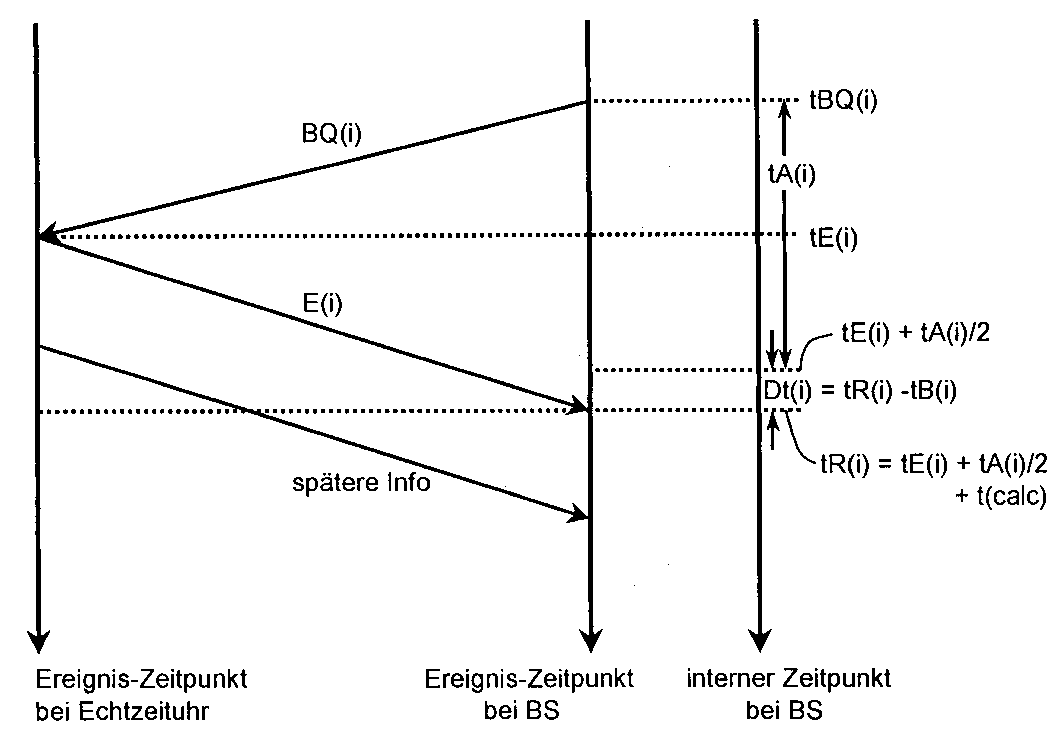
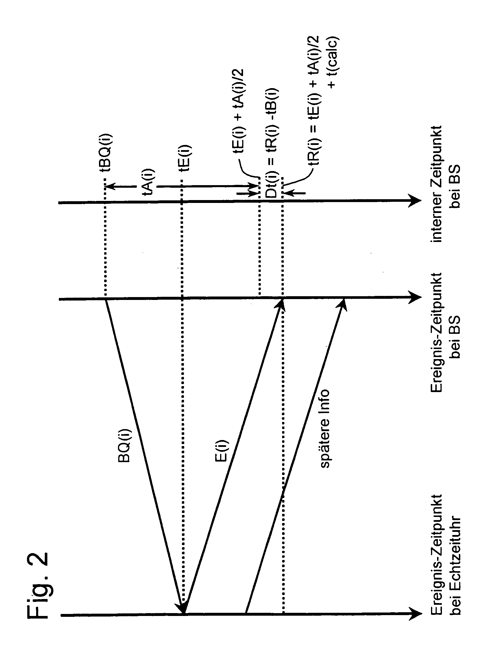
[0024]The invention provides a synchronization method and system for clock sources in communications systems.

[0025]Devices with such clock sources can be synchronized and the method for synchronizing them allows devices with clock sources to be operated reliably, without needing to be continually connected to a high-precision reference clock source. Furthermore, there is no need for every device to have its own precision clock source, with a high timing accuracy.

[0026]In addition, the capability to allow simple synchronization in Internet protocol (IP) lines or ATM lines without using very high precision clock sources in all the devices in the communications network is particularly advantageous.

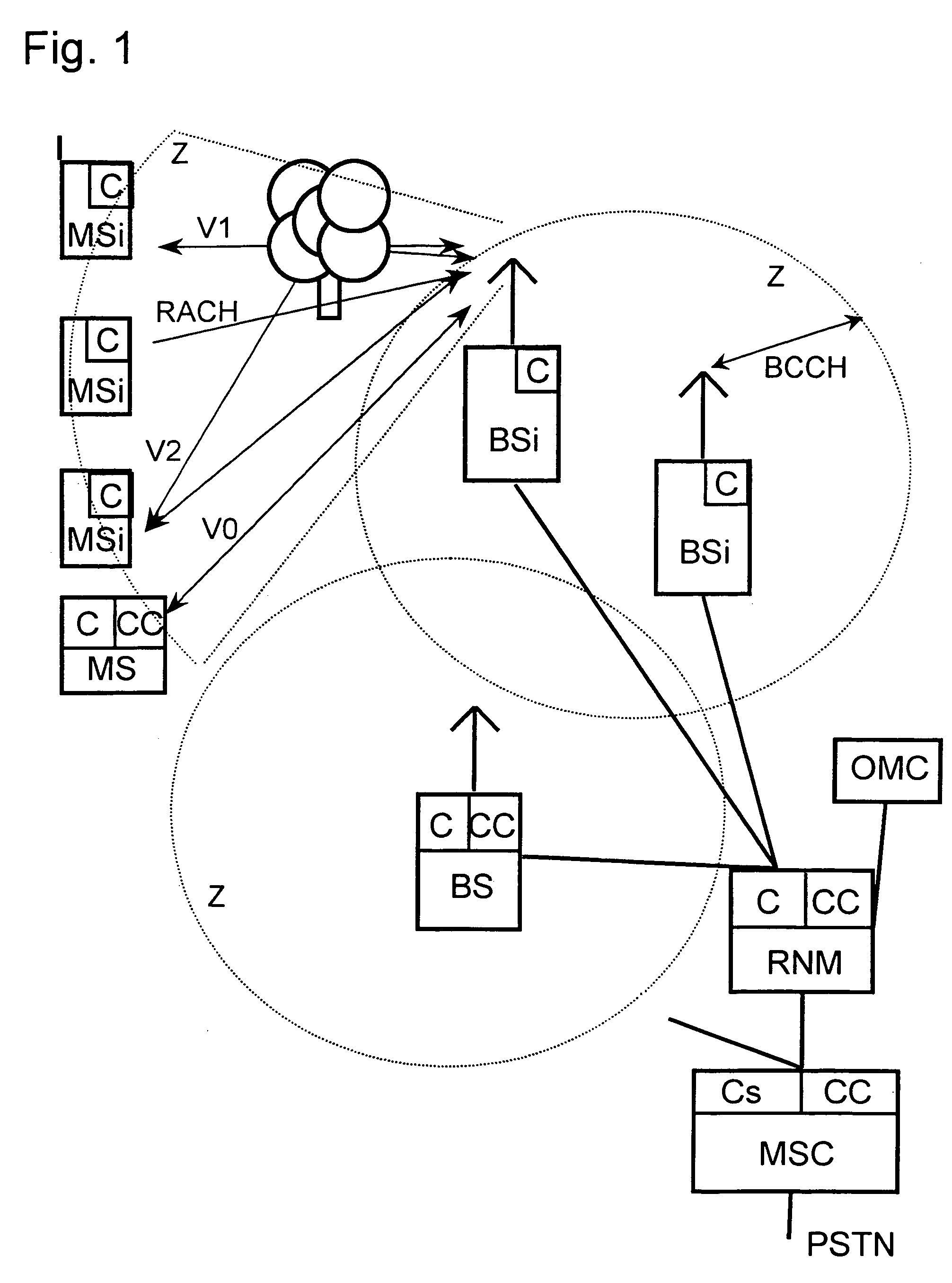
[0027]The mobile radio system illustrated in FIG. 1, as an example of a known radio communications system, comprises a large number of base station control devices or mobile switching centers MSC, which are networked with one another and provide access to a landline network PSTN. Furthermore,...


PUM


Abstract

The invention relates to a method for synchronization of clock sources in a communications system, in particular a radio communications system, having a large number of devices (PSTN, MSC, RNM, BSi, MSi, OMC) which communicate directly or indirectly with one another and have reference clock sources (Cs) for their operation.
In order to overcome aging effects or timing errors in the clock sources (C), the invention proposes the clock sources (C) of one or more communicating devices (MS, BS, RNM) be synchronized by means of asynchronous signaling from at least one reference clock source (Cs). This even allows devices with clock sources that are becoming old to be operated reliably. Furthermore, in particular, there is no need for every device to have its own high-precision clock source (CS). Use is particularly advantageous in communications systems in which no reference clock is transmitted via a landline network.

Description


Claims


Application Information

Patent Timeline
Owner HMD GLOBAL
Learn More