
Color filter substrate and display device

a display device and substrate technology, applied in the direction of liquid/fluent solid measurement, volume metering, instruments, etc., can solve the problems of color filter not being used for display purposes anymore, thin and lightweight display devices with comparatively low power dissipation, and lcds are relatively small, so as to reduce the unwanted deterioration of display quality

Active Publication Date: 2006-03-21
SHARP KK
View PDF8 Cites 7 Cited by
  • Summary
  • Abstract
  • Description
  • Claims
  • Application Information

AI Technical Summary

Benefits of technology

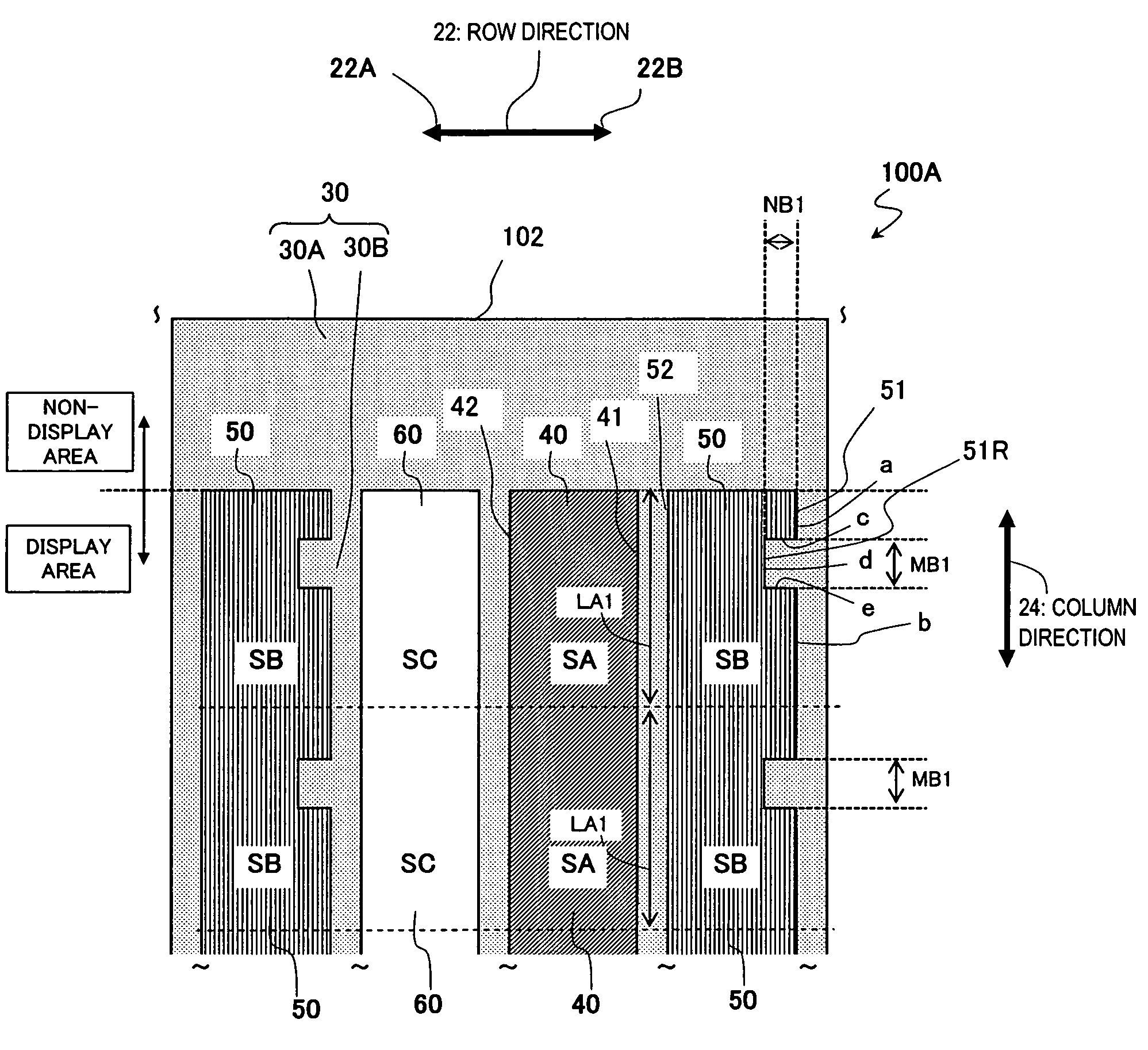
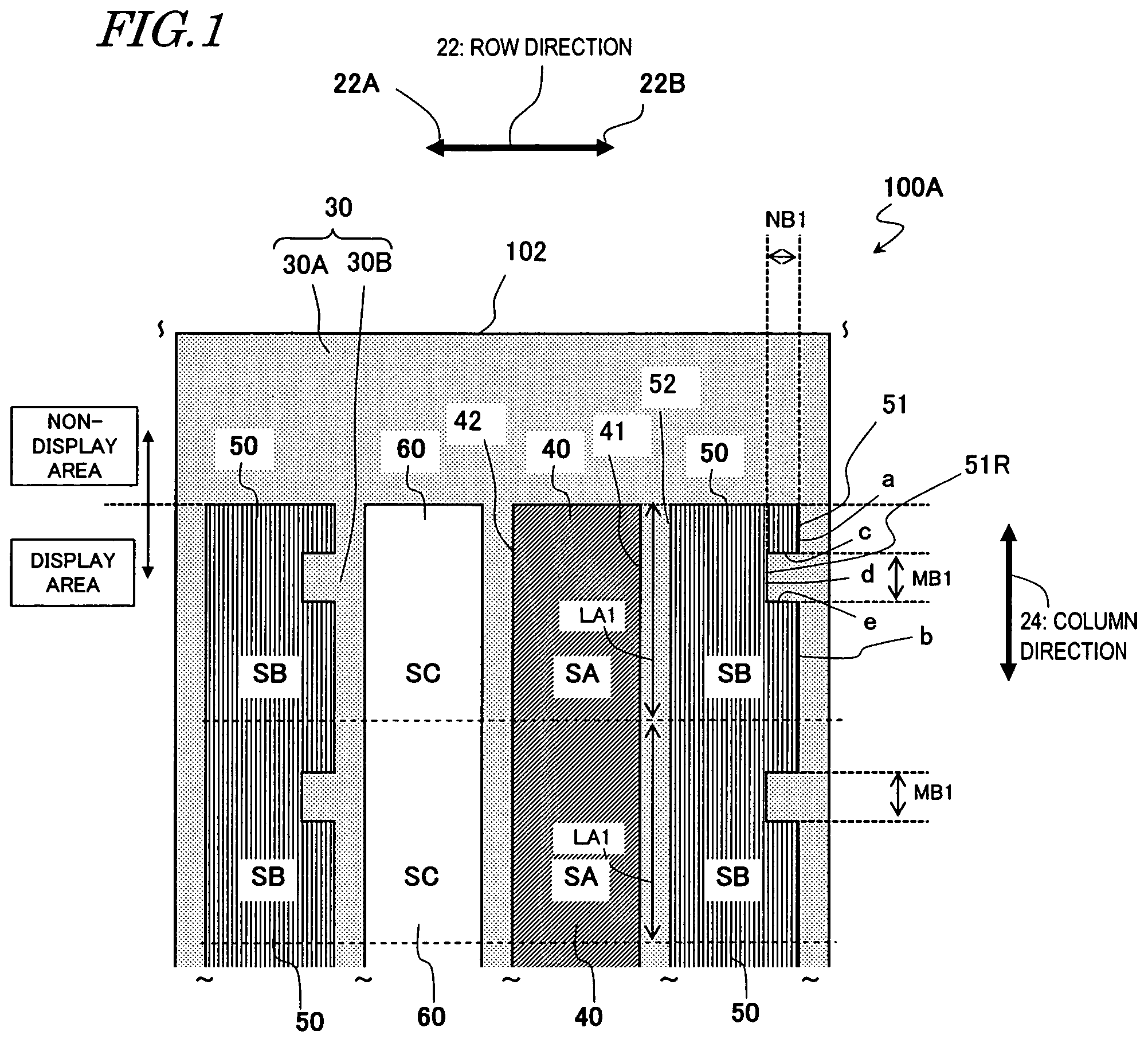
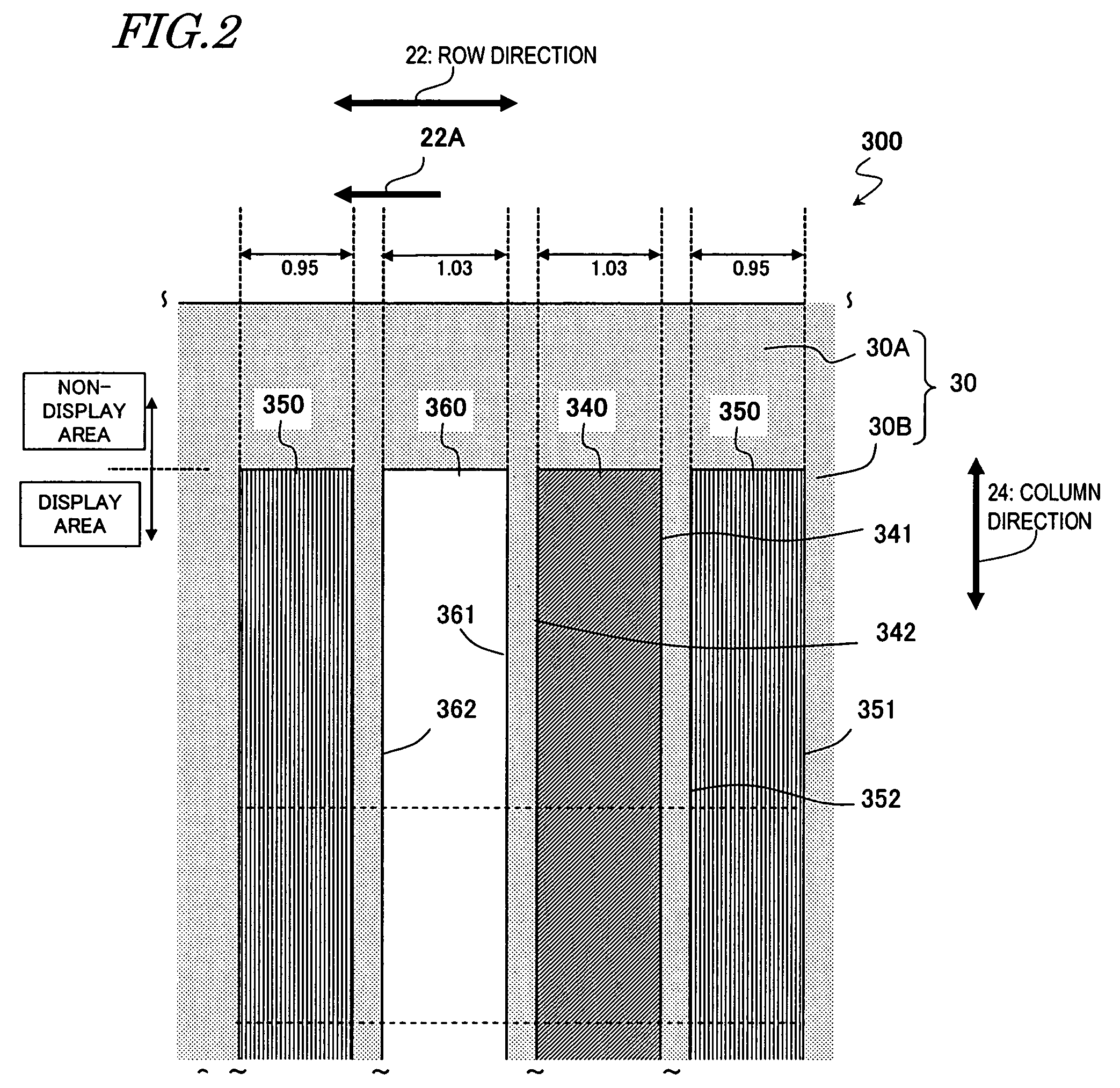
[0015]In order to overcome the problems described above, preferred embodiments of the present invention provide a color filter substrate, in which each set of color filters in multiple different colors have mutually different areas but which can still minimize the unwanted deterioration in display quality even in case of misalignment, and also provide a display device including such a color filter substrate.
[0051]Various preferred embodiments of the present invention provide a color filter substrate, which minimizes the deterioration in the display quality of a color display device, and also provide a display device including such a color filter substrate. That is to say, according to various preferred embodiments of the present invention, not only the decrease in pixel aperture ratio but also the deterioration of desired color balance (i.e., decrease in white chromaticity) due to some misalignment can be minimized.

Problems solved by technology

LCDs are relatively small, thin and lightweight display devices with comparatively low power dissipation.
However, in fabricating a liquid crystal display device by bonding a color filter substrate and an active-matrix substrate together, misalignment may happen.
As a result, some of the color filters cannot be used for display purposes anymore.
However, such a method is not preferred because the effective pixel area ratio (i.e., the aperture ratio) would decrease in that case.
Actually, though, those problems may arise not only in the display device described above but also in any other type of display device in which the misalignment of a color filter substrate from the other substrate affects the pixel aperture ratio.

Method used


Image

  • Color filter substrate and display device
  • Color filter substrate and display device
  • Color filter substrate and display device

Examples


Embodiment Construction

[0068]Hereinafter, color filter substrates according to various preferred embodiments of the present invention will be described with reference to the accompanying drawings. A color filter substrate according to any of various preferred embodiments of the present invention is preferably used in a display device including pixels that are arranged in a matrix so as to define columns of pixels in a column direction and rows of pixels in a row direction, respectively. Also, in a color filter substrate according to every preferred embodiment of the present invention, the areas of its color filters are adjusted on a color-by-color basis. That is to say, the area of a color filter in one color is different from that of a color filter in another color. In the following preferred embodiments, the present invention will be described as being applied to a color filter substrate including color filters that are preferably arranged in stripes for use in an active-matrix-addressed liquid crystal ...


PUM


Abstract

A color filter substrate for a display device includes pixels arranged in columns and rows. The substrate includes color filters, each being associated with one of the pixels and including at least two A-color filters in a first color and at least two B-color filters in a second color. Each row is associated with a group of color filters including at least one of the A-color filters and at least one of the B-color filters. Each of the A-color and B-color filters has first and second sides defining a width in the row direction. The area SA of each A-color filter is greater than the area SB of each B-color filter. The first side of each B-color filter has at least one recess, and the first side of each B-color filter has a shape that is defined by forming a recess on the first side of each A-color filter toward the second side thereof in the row direction.

Description

BACKGROUND OF THE INVENTION[0001]1. Field of the Invention[0002]The present invention relates to a method for fabricating a color filter substrate for use in a color liquid crystal display (LCD) and other display devices.[0003]2. Description of the Related Art[0004]LCDs are relatively small, thin and lightweight display devices with comparatively low power dissipation. By taking advantage of these features, LCDs are currently used extensively in a broad variety of electronic appliances. Among other things, active-matrix-addressed LCDs with switching elements are used particularly widely in office automation (OA) appliances such as personal computers, audiovisual (AV) appliances such as TV sets, and cell phones. Meanwhile, the size, definition, effective pixel area ratio (i.e., aperture ratio), color purity and other quality parameters of LCDs have recently been increased or improved significantly.[0005]The structure of a normal active-matrix-addressed LCD will be described with refe...

Claims


Application Information

Patent Timeline
IPC IPC(8): H01L31/0376H01L31/20G02B5/20G02F1/1335
CPCG02F1/133514G02F2201/40G01F15/14G01D11/26
Inventor TOKUDA, TSUYOSHITSUBATA, TOSHIHIDEYAGI, TOSHIFUMI
Owner SHARP KK
Learn More