
Inertia actuation for robotic gripper mechanism

a robotic and mechanism technology, applied in the field of robot gripper mechanisms, can solve the problems of limiting the amount of force that can be generated within the time window of a given motor, and achieve the effect of increasing the force and speed of the gripping action and increasing the inertia

Inactive Publication Date: 2006-03-21
ORACLE INT CORP
View PDF7 Cites 41 Cited by
  • Summary
  • Abstract
  • Description
  • Claims
  • Application Information

AI Technical Summary

Benefits of technology

[0008]The present invention provides a method for gripping objects by means of a robotic gripper mechanism, wherein the gripping mechanism comprises gripping jaws, a wedge actuator between the gripping jaws, wherein the wedge actuator moves the gripping jaws together and apart as it slides backward and forward, and a motor that moves the wedge actuator by means of a connecting leadscrew. The method comprises applying current to the motor so that the motor reaches maximum operating speed before the gripper mechanism comes into contact with any object. When the gripping jaws contact an object, e.g., media cartridge, they collapse over the object, gripping it. The inertia from the rotating mass of the motor increases the force and speed of the gripping action. In another embodiment, a flywheel may be added to the leadscrew to provide additional rotating mass and increase the inertia before contact.

Problems solved by technology

In addition to the time delay, the force produced by the motor must be generated from, a dead stop, thus limiting the amount of force that can be generated within the time window for a given sized motor.

Method used


Image

  • Inertia actuation for robotic gripper mechanism
  • Inertia actuation for robotic gripper mechanism
  • Inertia actuation for robotic gripper mechanism

Examples


Embodiment Construction

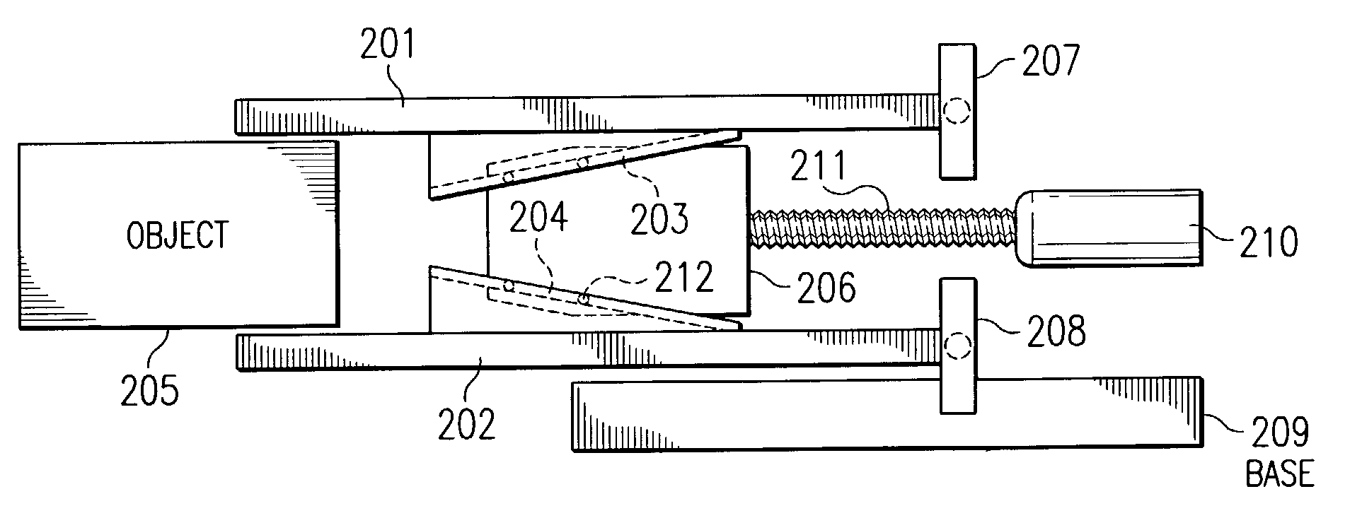
[0014]Referring now to the figures, and more specifically to FIG. 1, a schematic diagram illustrating a typical hinged gripper robot is depicted in accordance with the prior art. Typical robotic grippers for automated data storage libraries are slow speed pinching mechanisms for gripping onto a standard sized box shaped media cassette. The size of the cassette usually dictates a range of movement of the gripper jaws and the simplest solution for proper movement of the jaws is to hinge them in the rear and provide an actuator to push them apart and pull them together to pinch an object.

[0015]FIG. 1 depicts a pair of hinged jaws 101 and 102 supported by a pivot 103 in the rear and a driving linkage 104 in the front. A motor 105 is connected to a screw 106, which, when rotated, drives a nut 107 connected to the linkage 104. This typical gripper has several limitations.

[0016]First, the jaws 101–102, because of their pivot point 103, will not remain parallel to each other as the cassette...


PUM


Abstract

A method for gripping objects by means of a robotic gripper mechanism is provided, wherein the gripping mechanism comprises gripping jaws, a wedge actuator between the gripping jaws, wherein the wedge actuator moves the gripping jaws together and apart as it slides backward and forward, and a motor that moves the wedge actuator by means of a connecting leadscrew. The method comprises applying current to the motor so that the motor reaches maximum operating speed before the gripper mechanism comes into contact with any object. When the gripping jaws contact an object, e.g., media cartridge, they collapse over the object, gripping it. The inertia from the rotating mass of the motor increases the force and speed of the gripping action. In another embodiment, a flywheel may be added to the leadscrew to provide additional rotating mass and increase the inertia before contact.

Description

BACKGROUND OF THE INVENTION[0001]1. Field of the Invention[0002]The present invention relates generally to robotic gripper mechanisms, and more specifically to an improved actuator for the gripping action.[0003]2. Background of the Invention[0004]Typical robotic grippers (also known as end effectors) for automated data storage libraries are slow-speed pinching mechanisms for gripping onto a standard sized box-shaped media cassette. The size of the cassette usually dictates the range of movement of the gripper jaws. The simplest solution for proper movement of the jaws is to hinge them in the rear and provide an actuator to push them apart and pull them together in order to grip an object. Typically, a motor is used to drive a nut and linkage arrangement that moves the gripper finger together or apart.[0005]Typical gripper mechanisms do not ramp up the motor to apply force to the jaws until the gripper makes contact with an object. Generally, the gripper has a limited time frame (e.g...

Claims


Application Information

Patent Timeline
Patent Type & Authority Patents(United States)
IPC IPC(8): B25J15/00
CPCB25J15/028B25J9/1612
Inventor OSTWALD, TIMOTHY C.
Owner ORACLE INT CORP
Learn More