
Method for controlling ignition parameters of a spark plug for internal combustion engine

a technology of internal combustion engine and ignition parameters, which is applied in the direction of machines/engines, mechanical equipment, instruments, etc., can solve the problems of poor ignition quality of air/, high rate of recirculation gas, and the inability to determine which parameter (voltage, duration or intensity of the arc)

Inactive Publication Date: 2006-03-21
INST FR DU PETROLE +1
View PDF5 Cites 5 Cited by
  • Summary
  • Abstract
  • Description
  • Claims
  • Application Information

AI Technical Summary

Benefits of technology

[0017]The present invention overcomes the aforementioned drawbacks by providing an ignition device that replaces the ignition coil and allows easy control of all the parameters relative to the electric arc of the spark plug.

Problems solved by technology

Furthermore, in difficult contexts (lean mixture, high rate of recirculated gas, .
. . ) leading to a poor ignition quality of the air / fuel mixture or even to the absence of ignition, it is impossible to determine which parameter (voltage, duration or intensity of the arc, .
. . ) could be concerned, which consequently leads to use coils with maximum capacities in all the domains, thus increasing its cost price.
After a short primary supply time, the command actuates the switch in open position for a short time, which interrupts supply of the primary and leads to a progressive current drop thereof.
Furthermore, as in the case of conventional ignition coils, it is impossible to monitor the working parameters of this ignition, such as the secondary voltage or the duration of the arc or its intensity, to be able to correct them in a case of a deviation in relation to reference values.

Method used


Image

  • Method for controlling ignition parameters of a spark plug for internal combustion engine
  • Method for controlling ignition parameters of a spark plug for internal combustion engine
  • Method for controlling ignition parameters of a spark plug for internal combustion engine

Examples


Embodiment Construction

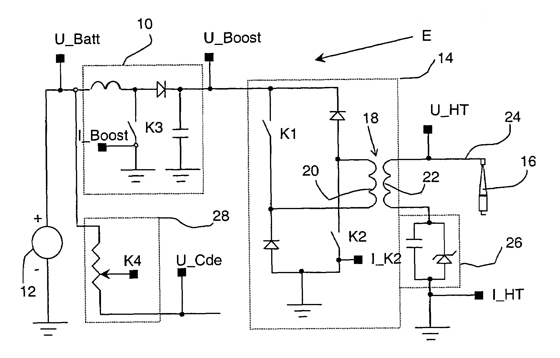
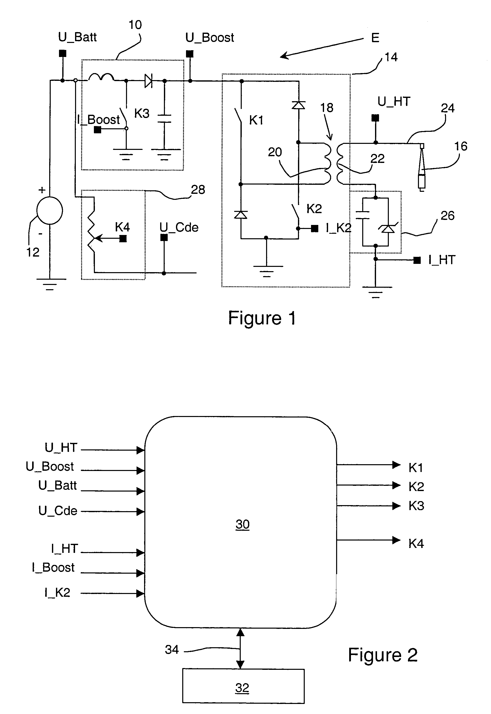
[0032]FIG. 1 shows an ignition emulator E for internal-combustion engine, notably of a motor vehicle, comprising a voltage converter 10 which converts the voltage coming from a battery 12 up to a voltage of 600 V, which is preferably up to 400 V, and a chopper 14 for generating a high voltage on a spark plug 16. The high voltage generates an electric arc or spark at the electrodes of this spark plug, thus allowing ignition of an air / fuel mixture present in a combustion chamber of an internal-combustion engine.

[0033]As can be clearly seen in FIG. 1, converter 10 comprises an interrupter switch K3 switching device allowing varying the voltage at the output thereof until the desired voltage to be applied to chopper 14 is reached.

[0034]Chopper 14, whose input is connected to the output of converter 10, comprises a transformer 18 equivalent to an ignition coil with a primary 20 and a secondary 22.

[0035]Primary 20 comprises two interrupter switches, an upper interrupter switch K1 allowing...


PUM


Abstract

The invention is a method for controlling ignition parameters of a spark plug (16) for an internal-combustion engine whose ignition is controlled by an engine control calculator, with the spark plug receiving a high voltage (U_HT) and a current (I_HT) from an ignition emulator (E). The method establishes a target current and / or voltage values (Ucible_HT, Ucible_Boost, Icible_HT, Icible_Boost) to obtain the desired electric arc at the spark plug electrodes, stores the target values in a parametering unit (32), measuring at regular intervals, after an ignition command by the calculator, at least one of a voltage (U_HT, U_Boost, U_Batt) and current (I_HT, I_Boost) parameter coming from the emulator, comparing the parameters with the target values, and when variation occur between the measured parameters and the target values, adjusting the parameters to reach the target values for controlling the ignition parameters of a spark plug for an internal-combustion engine. The spark plug receives a voltage (U_HT) and a current (I_HT) from ignition emulator (E). At least one interruption means (K1, K2, K3) control the voltage applied to the spark plug.

Description

BACKGROUND OF THE INVENTION[0001]1. Field of the Invention[0002]The present invention relates to a method for controlling ignition parameters of a spark plug for an internal-combustion engine and to an ignition device using such a method.[0003]2. Description of the Prior Art[0004]It is already well-known to use ignition coils to generate a high voltage applied to a spark plug in an engine. The high voltage applied to the spark plug creates, at the electrodes thereof, an electric arc whose energy is used to ignite an air / fuel mixture present in the combustion chamber of the engine.[0005]These ignition coils generally consist of a primary winding, referred to as a primary, connected to a source of direct current, such as the battery of a motor vehicle, and a secondary winding, referred to as a secondary, connected to a spark plug and which, under the effect of the voltage applied to the primary, generates a high voltage which is applied to the spark plug so as to form, at the electrod...

Claims


Application Information

Patent Timeline
Patent Type & Authority Patents(United States)
IPC IPC(8): F02P1/00F02P3/05F02P3/08F02P17/12
CPCF02P3/051F02P17/12F02P3/0884
Inventor METZELARD, OLIVIER
Owner INST FR DU PETROLE
Learn More