
Internal spur gear drive

a technology of spur gear drive and internal spur gear, which is applied in the field of mechanical systems, can solve the problems of reducing the power output of the engine, reducing the efficiency of the propeller, and the operation of the typical aircraft reciprocating engine at relatively low (and inefficient) rpm

Inactive Publication Date: 2006-03-14
REDFERN DANIEL J
View PDF13 Cites 10 Cited by
  • Summary
  • Abstract
  • Description
  • Claims
  • Application Information

AI Technical Summary

Benefits of technology

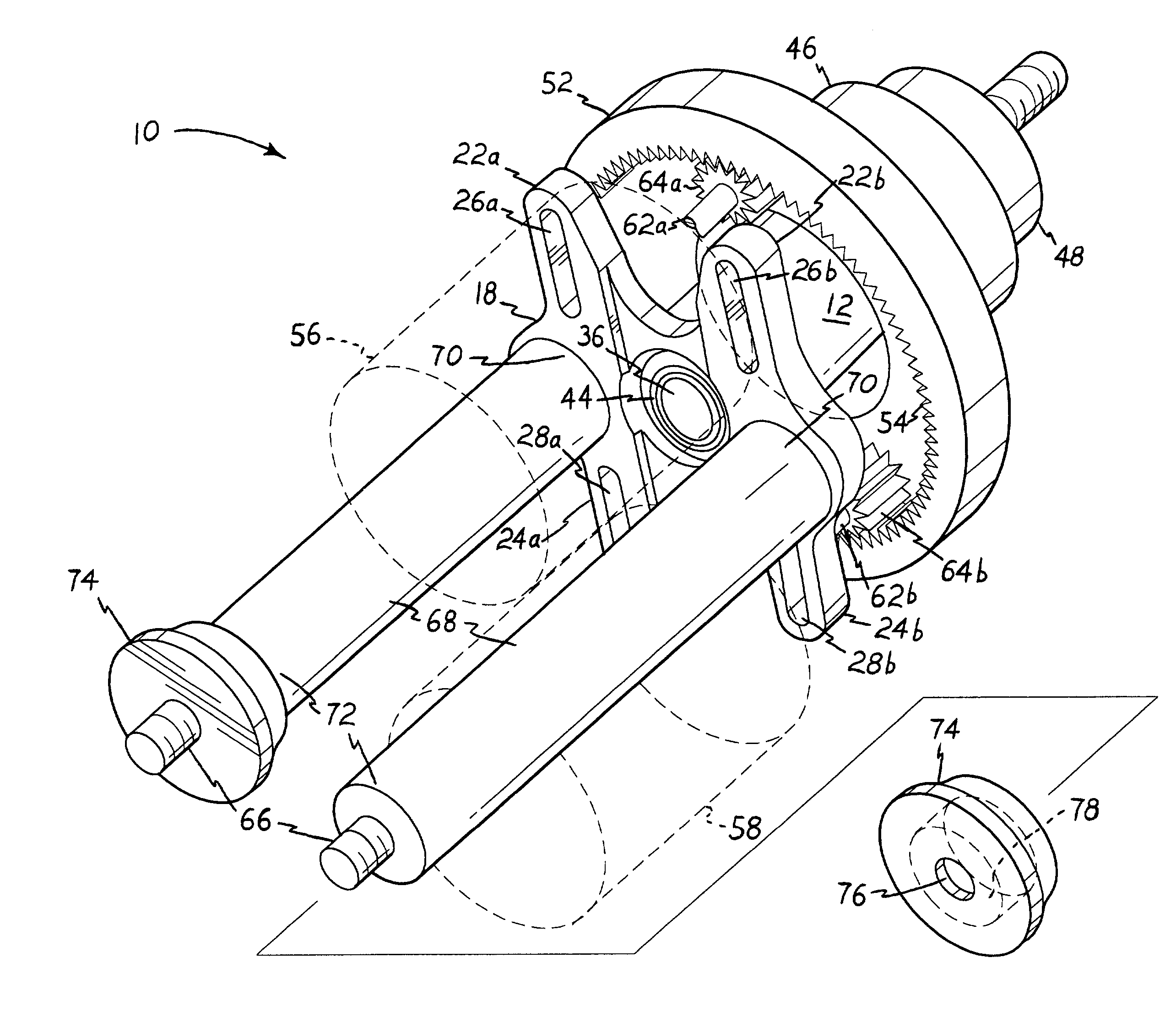
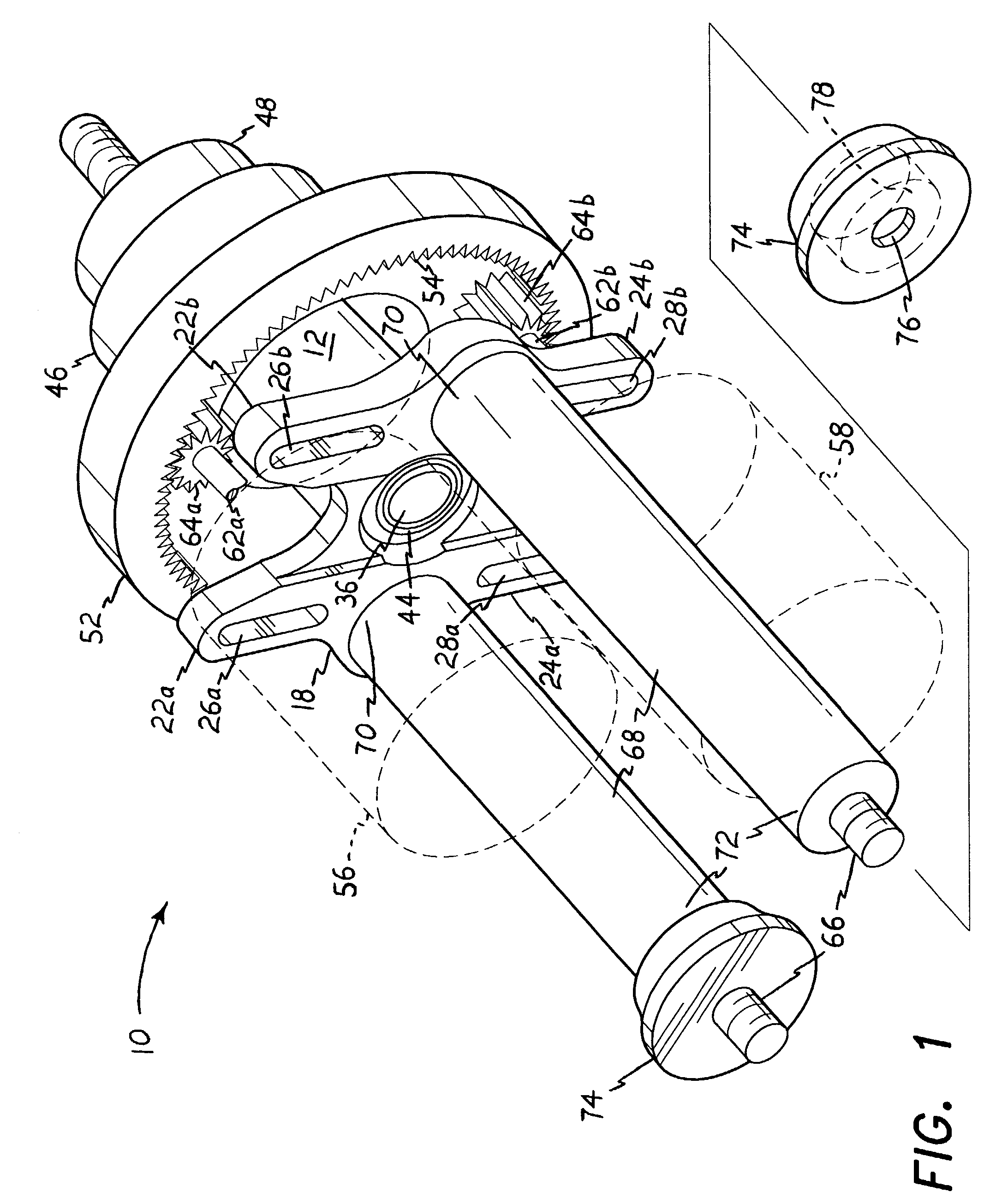
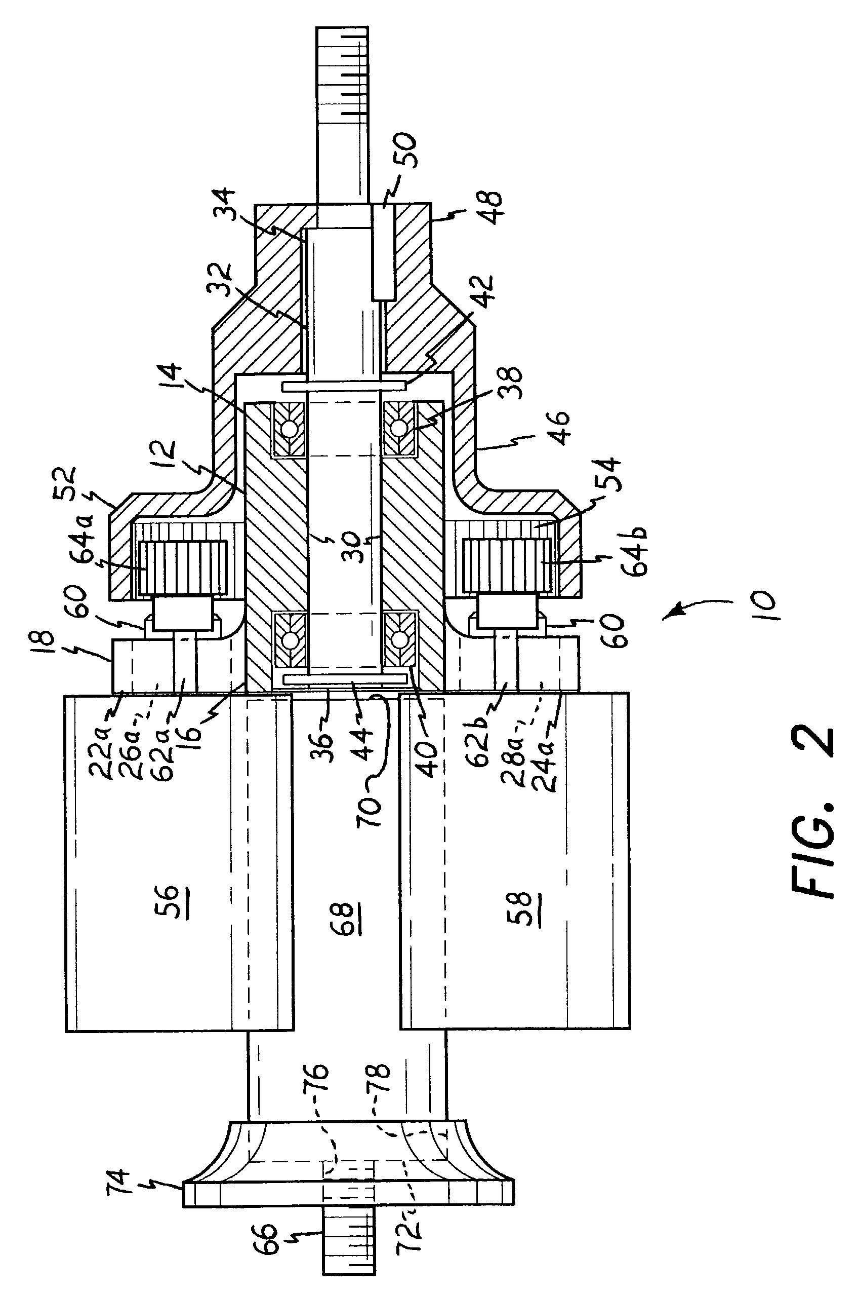
[0023]The present invention comprises a spur gear drive system, having at least one (and preferably two or more) externally toothed pinion spur gears, each driven by a corresponding motor. The external pinion gear(s) engage(s) the internal teeth of a larger, surrounding, generally bell-shaped drive, which accepts power from the smaller externally toothed pinion gears. The opposite end of the bell drive is keyed or otherwise immovably secured to an output shaft, which is used to apply the rotary power as desired. The motor(s) is / are secured in place by a drive base mount, which includes a series of motor mounting lugs extending generally radially therefrom. The lugs are radially slotted, thereby permitting the motor or motors to be adjusted radially inwardly or outwardly relative to the central drive shaft. This allows adjustment for gear lash and wear, and also allows the operator to change the motor pinion gears for larger or smaller diameter gears as desired, thereby changing the gear ratio as desired.
[0026]It is another object of the invention to provide such a mechanism in which the position(s) of the motor(s) may be adjusted radially upon their mounts, thereby providing adjustment for gear lash and allowing different diameter pinion gears to be installed for different gear ratios.
[0029]It is an object of the invention to provide improved elements and arrangements thereof for the purposes described which is inexpensive, dependable and fully effective in accomplishing its intended purposes.

Problems solved by technology

If this limit is exceeded, the tips of the propeller blades reach the speed of sound, which greatly lowers the efficiency of the propeller due to the energy required in producing the resulting shock or compression wave.
As a result, typical aircraft reciprocating engines operate at relatively low (and inefficient) RPM, in order to avoid the weight, complexity, maintenance, and possible reliability issues which would result from a gear reduction system.
When internal combustion engines are used, this results in a need for some form of muffler on the engine, which can reduce the power output of the engine to the extent that flight performance is reduced to marginal levels.
However, such electric motors are not without their drawbacks, as well.
Generally speaking, the relatively small electric motors used do not produce equivalent amounts of torque and power in comparison to internal combustion engines (particularly two stroke cycle engines) of comparable size and weight.
This leads to problems with propeller efficiency, as noted further above.
However, the relatively high operating RPM is a necessary evil, as otherwise the motor may not produce sufficient torque to enable the model to fly.
These speed reduction gearing systems which are known to the present inventor, tend to be less than optimally reliable and also require relatively tedious and time consuming adjustment for gear lash, gear ratio changes (if such adjustment is available at all), and other factors which occur due to normal operation and wear.
The Hoffmann et al. system does not provide any means of adjusting the gear ratios or gear lash of the system, nor standoffs for mounting the assembly to a firewall or other planar structure.
Also, Shiroyama makes no provision for adjusting for gear lash nor for changing gear ratios in his gear system.

Method used


Image

  • Internal spur gear drive
  • Internal spur gear drive
  • Internal spur gear drive

Examples


Embodiment Construction

[0037]The present invention is an internal spur gear drive, including a mounting base which may be configured for adjustable attachment of multiple motors thereto. The motors each have a drive shaft with an externally toothed pinion spur gear extending therefrom, which engage the internal teeth of a drive bell which surrounds and protects the pinion gears. The drive bell is secured to a drive shaft which provides power output from the mechanism.

[0038]FIGS. 1 and 2 of the drawings respectively provide a perspective view and a side elevation view in section of the present spur gear drive 10. The heart of the present drive system 10 comprises a drive shaft housing 12 having a distal first end 14 and an opposite second end 16 which is integrally attached to a mounting base 18. The mounting base 18 is a generally planar structure, oriented substantially normal to the axis of the drive shaft housing 12. The mounting base 18 provides for the attachment of the assembly to another structure ...


PUM


Abstract

An internal spur gear drive has a mounting base including one or more sets of motor mounting lugs extending therefrom, for attaching a corresponding number of drive motors thereto. A drive shaft housing containing a rotary drive shaft extends from the mounting base. A drive bell is affixed to the drive shaft distal end, and rotates therewith. The opposite end of the drive bell has an internally toothed ring gear extending therefrom. Each motor drives a pinion gear which engages the internal teeth of the drive bell ring gear to rotate the drive bell and thus rotate the drive shaft as well. The motor mounting lugs are slotted, allowing the motors to be adjusted radially relative to the drive shaft and drive bell ring gear. This provides adjustment for gear lash, as well as permitting different sizes of pinion gears to be installed on the motors for different gear ratios.

Description

BACKGROUND OF THE INVENTION[0001]1. Field of the Invention[0002]The present invention relates generally to mechanical systems for altering the rotational speed of a rotating device. More specifically, the present invention comprises a gear reduction drive having one or more internal pinion spur gears each driven by a separate motor, with each motor and pinion gear driving a larger, internally toothed ring spur gear turning at a slower RPM. The present gear reduction drive may be scaled to any practicable size and applied to any suitable machinery as desired, but is particularly well suited for reducing the output speed of relatively small electric motors used to power propeller driven model aircraft.[0003]2. Description of the Related Art[0004]Speed reduction drives for reducing the final output RPM of a rotary device, are well known. Typically, such devices are powered by a single prime mover (internal combustion or turbine engine, electric motor, etc.) and utilize a gear train (or...

Claims


Application Information

Patent Timeline
IPC IPC(8): F16H37/00B64D35/00F16H1/22H02K7/116H02K16/00
CPCF16H1/227H02K7/116Y10T74/19014H02K16/00
Inventor REDFERN, DANIEL J.
Owner REDFERN DANIEL J
Learn More