Polymer fibers, fabrics and equipment with a modified near infrared reflectance signature
a polymer fiber and near infrared reflectance technology, applied in the direction of dyeing process, dyeing solution, other domestic articles, etc., can solve the problems of high reflectance, color garments such as solid tan, and not meet the nir reflectance specifications for military applications, so as to reduce reflectance, improve dyeing or printing, and reduce the effect of reflection
- Summary
- Abstract
- Description
- Claims
- Application Information
AI Technical Summary
Benefits of technology
Problems solved by technology
Method used
Image
Examples
example 1
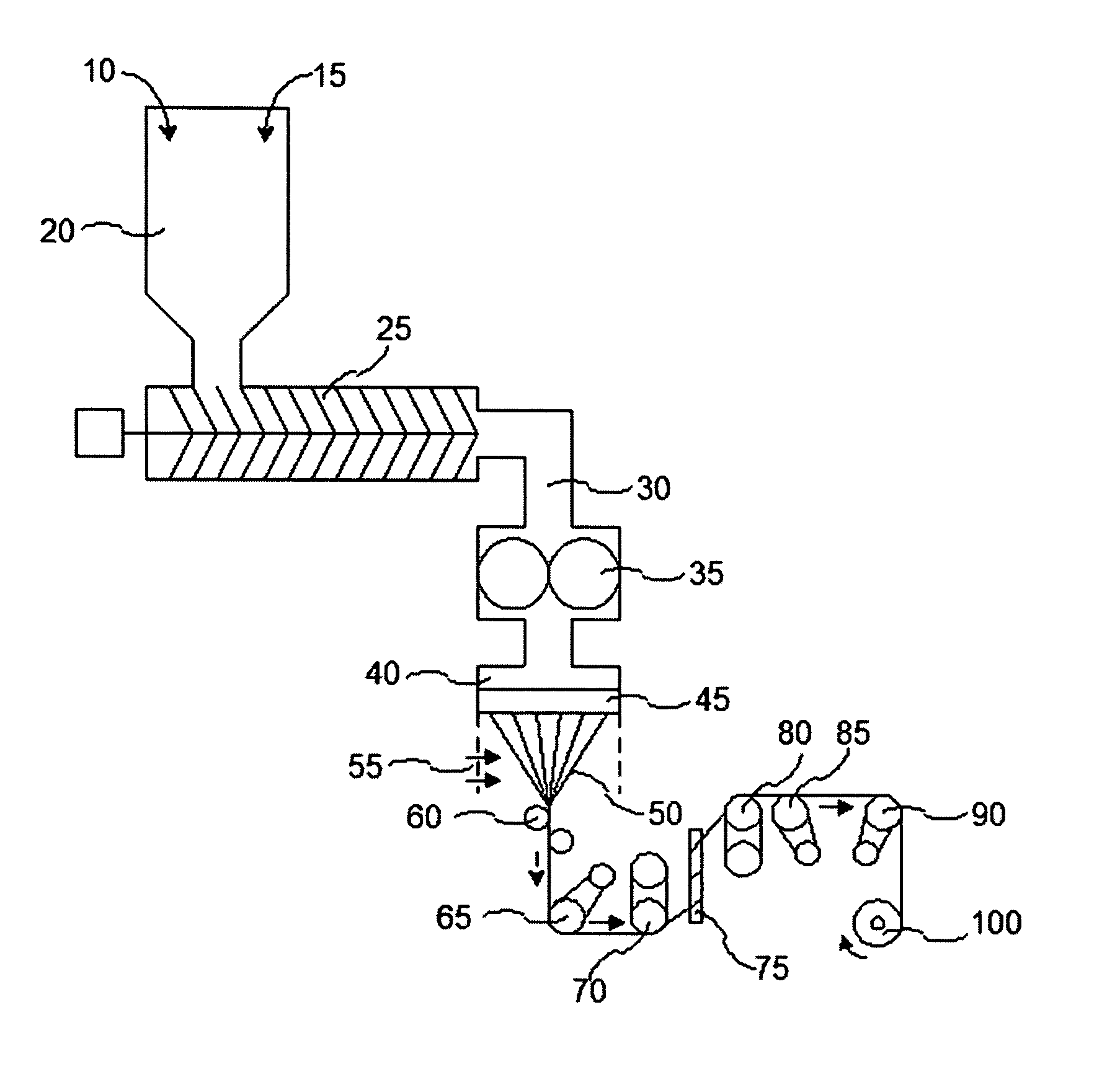
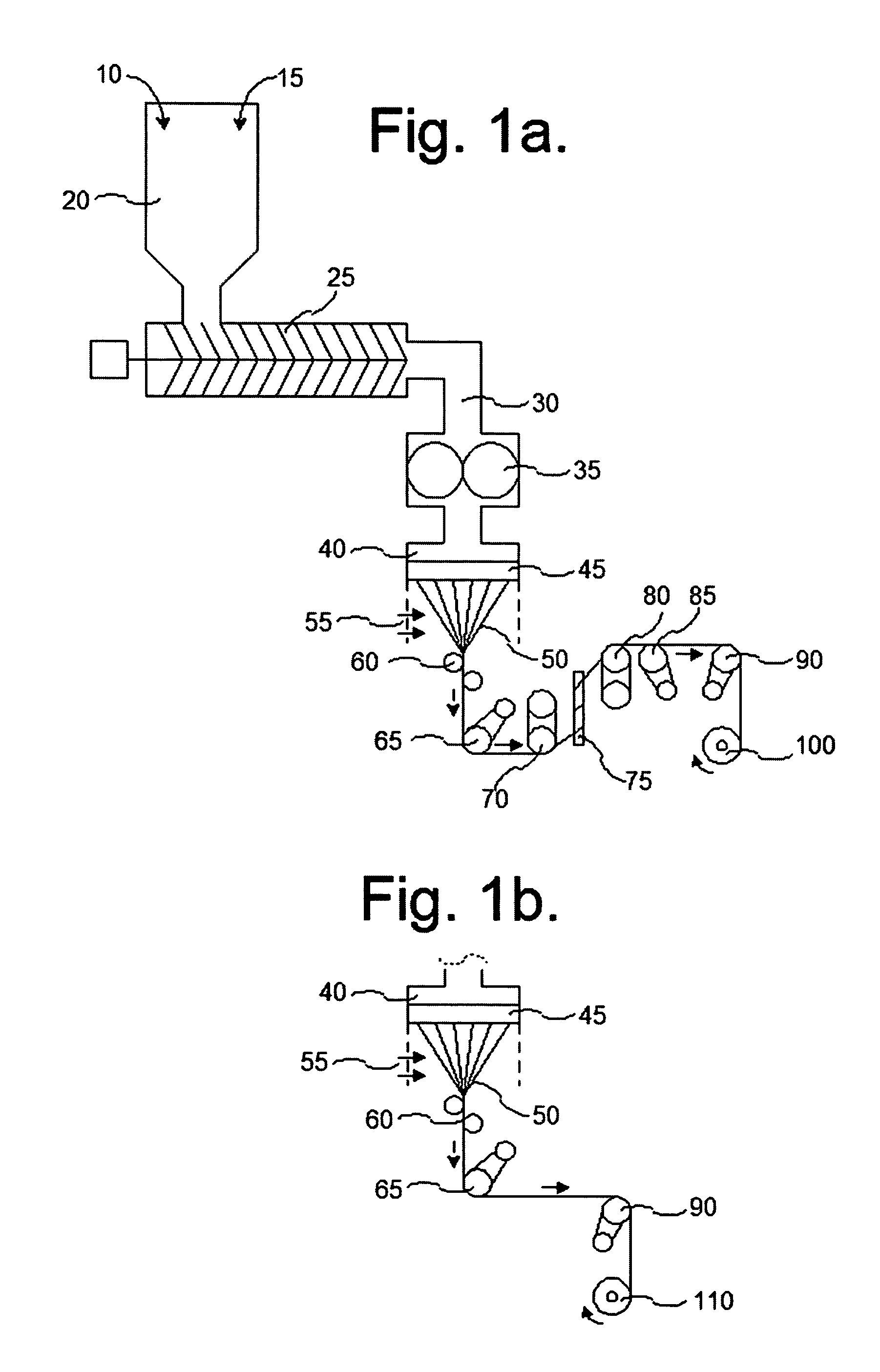
[0046]The yarn of the invention used to prepare fabric 410 (FIG. 4) was melt spun from nylon 6,6 polymer. This polymer was mixed with sufficient 1% carbon black in a nylon 6 matrix (AMERICHEM Inc, Product 11793-F1 Black) in the feed section of an screw melt extruder to prepare a yarn containing 70 ppm carbon black. Polymer was heated at 288° C. The molten polymer was extruded through a spinneret that was sized appropriately to control the production of a 494 denier (540 dtex) and 140 filaments of circular cross section. Freshly extruded filaments were quenched in a cross flow of conditioned air, converged into a yarn and a fiber finish was applied to the yarn. The feed roll controls spin orientation of the yarn. Feed roll surface speed was in the range of speeds between 550 and 800 meters per minute and typically between 640 and 700 meters per minute. This yarn was drawn in two stages. The first stage draw ratio was in the range between 1.8 and 3.2, more typically between 2.6 and 3....
example 2
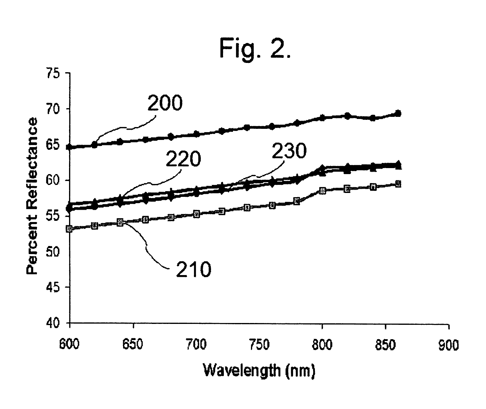
[0054]The effect of varied amounts of carbon black on the NIR reflectance of nylon 6,6 was carried out for the spectral region from 600 nm to 900 nm. A regression analysis of carbon black concentration from zero to 500 ppm was performed. For each concentration of carbon black, the average reduction in NIR reflection was measured in the spectral range 680 nm to 860 nm. These data showed an inverse proportionality to the carbon black concentration in nylon 6,6 air textured filaments. A regression analysis provided the following equation:
Log (ave. % NIR reflectance)=1.84−0.000976 (ppm carbon black).
Using this equation, a tailored modification to the NIR spectral signature of a filament, a yarn or a fabric is available in the range from 600 nm to 900 nm. These data are shown in Table 2.
[0055]
TABLE 2Effect of Carbon Black Concentration on NIR Reflectance forNylon 6,6 494-140 (3.5 dpf) With Circular Cross SectionCarbon BlackPercent NIRPercent NIRPercent NIRConcentrationReflectanceReflecta...
example 3
[0056]Nylon 6,6 polymer was mixed with sufficient 1% carbon black in a nylon 6 matrix (AMERICHEM Inc, Product 11793-F1 Black) in the feed section of a screw melt extruder to prepare a yarn containing either 35 or 70 ppm carbon black. The polymer was heated at 290° C. The molten polymer passed through a spinneret that produced a 120-20 round fiber. Freshly extruded filaments were quenched in a cross flow of conditioned air, converged into a yarn and a fiber finish was applied to the yarn. Yarn was drawn onto a feed roll then stretched 2.5× and 3.0× on the second stage roll (4673 mpm), and the yarn was then relaxed by 10.75% and placed on the winder (4200 mpm). The NIR reflectance data over the range of 600–900 nm are shown in Table 3.
[0057]
TABLE 3Effect of Carbon Black Concentration on NIR Reflectance forNylon 6,6 Yarn of 120-20 (6 dpf) With Circular Cross Sectional ShapeCarbon BlackPercent NIRPercent NIRPercent NIRConcentrationReflectanceReflectanceReflectanceNylon 6,6 polymer600–70...
PUM
| Property | Measurement | Unit |
|---|---|---|
| near infra-red reflectance | aaaaa | aaaaa |
| reflectance | aaaaa | aaaaa |
| IR reflectivity | aaaaa | aaaaa |
Abstract
Description
Claims
Application Information
 - R&D
- Intellectual Property
- Life Sciences
- Materials
- Tech Scout
- Unparalleled Data Quality
- Higher Quality Content
- 60% Fewer Hallucinations
Browse by: Latest US Patents, China's latest patents, Technical Efficacy Thesaurus, Application Domain, Technology Topic, Popular Technical Reports.
© 2025 PatSnap. All rights reserved.Legal|Privacy policy|Modern Slavery Act Transparency Statement|Sitemap|About US| Contact US: help@patsnap.com


