
Omnidirectional reading of two-dimensional symbols

a two-dimensional symbol and optical scanning technology, applied in the field of optical scanning of two-dimensional bar code symbols, to achieve the effect of reducing the absolute value of the angl

Inactive Publication Date: 2006-03-07
SYMBOL TECH INC
View PDF32 Cites 17 Cited by
  • Summary
  • Abstract
  • Description
  • Claims
  • Application Information

AI Technical Summary

Benefits of technology

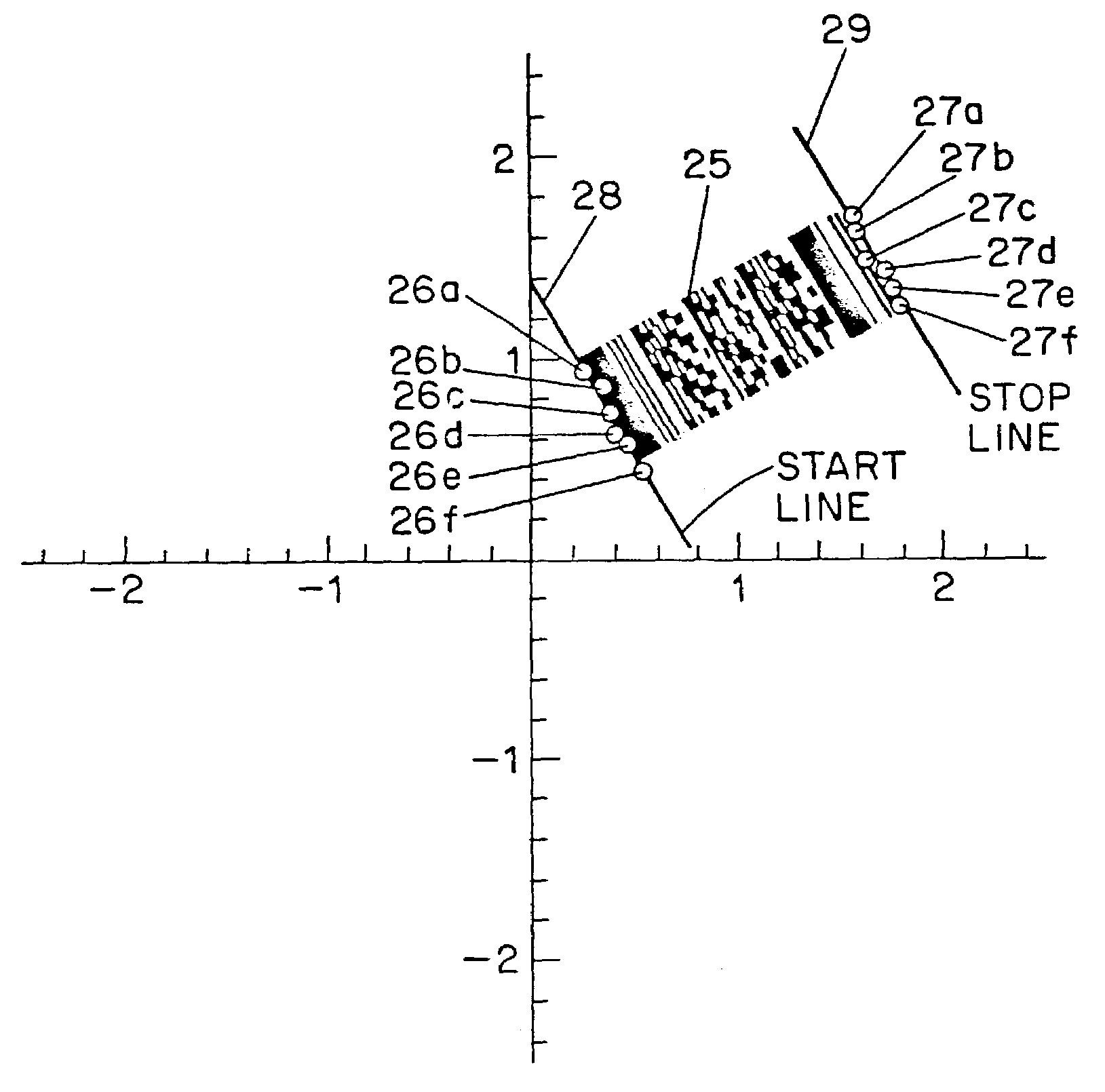
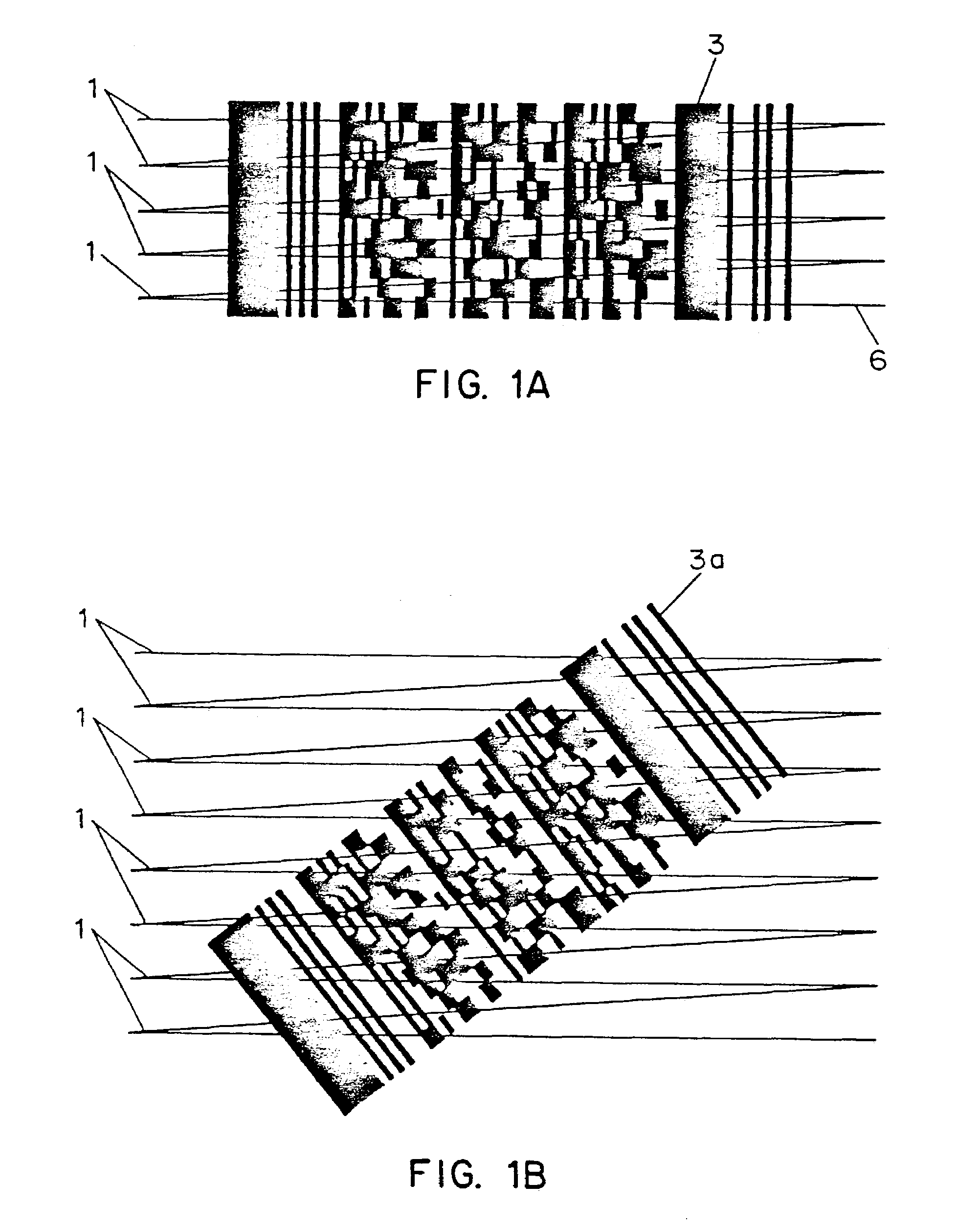
[0015]In accordance with these and other objects, provided is a method and apparatus for aligning a scan pattern to a two dimensional bar code having parallel rows of codewords, wherein the two dimensional bar code is scanned with a scanning pattern oriented such that a plurality of lines thereof cross the bar code rows, a determination is made as to if there is a non-zero angle between at least one of the plurality of lines and the rows by decoding codewords in rows intersected by the at least one line and the orientation of the scanning pattern is adjusted to reduce the absolute value of the angle.
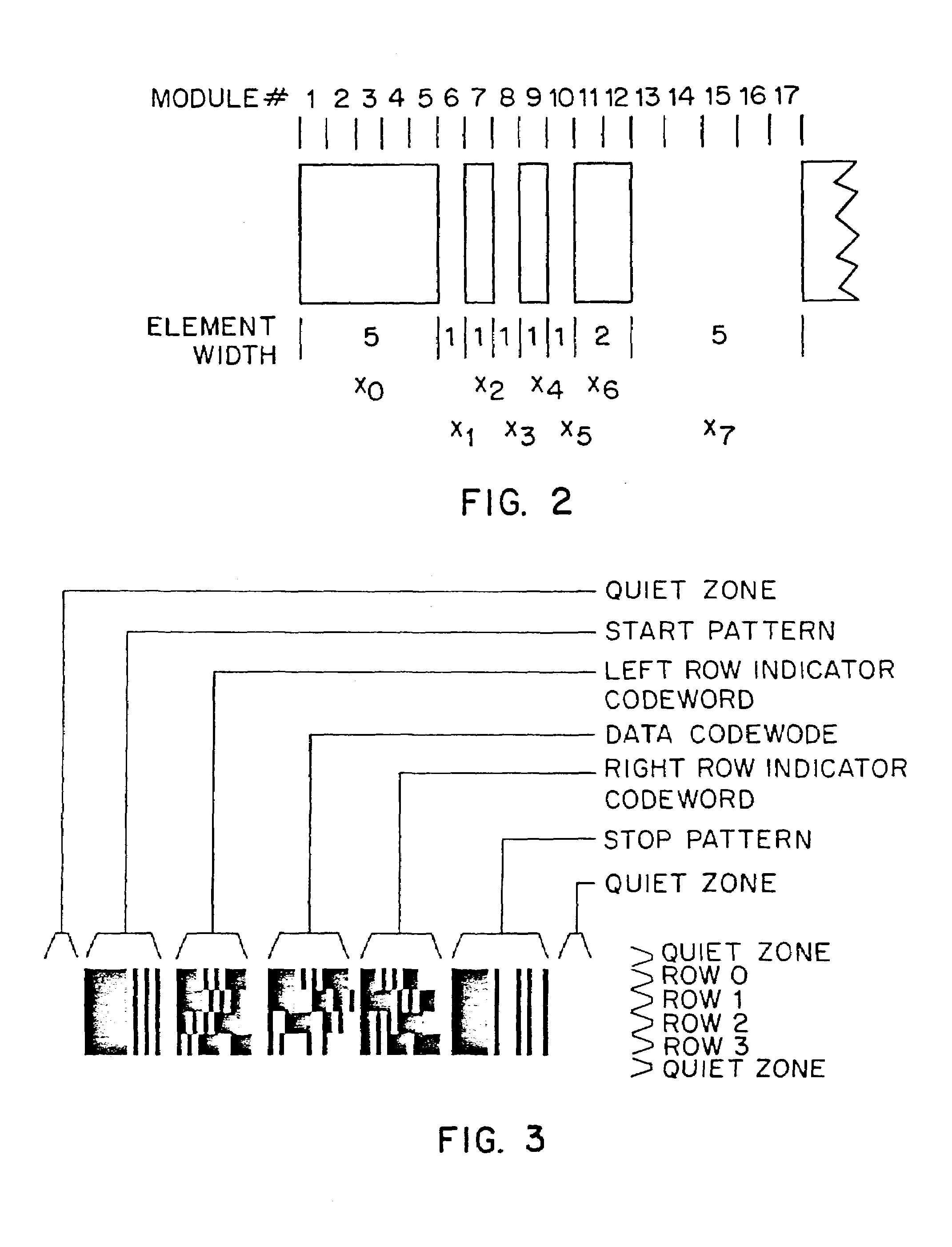
[0016]The bar code in PDF417 has row indicator codewords in each row and the method can use the decoding of the row indicator codewords read by the at least one line to determine the slope of the angle therefrom. The bar code in PDF417 has codewords which are divided into a plurality of clusters and wherein each row uses codewords of only one cluster and the method can use codewords read by the at least one line to determine the cluster of each codeword and determine the slope of the angle therefrom. The bar code in PDF417 has a fixed number of module widths in each codeword and a row height which is a function of the module width and the number of codewords per row encoded therein and the method can determine the magnitude of the angle from the number of codewords per row and the aspect ratio of the row height to the module width.
[0018]The system for aligning a scan pattern has a pattern generator for generating a scanning pattern oriented to scan the two dimensional bar code such that a plurality of scan lines cross the bar code rows, a processor for determining if there is a non-zero angle between at least one of the plurality of lines and the rows by decoding codewords in rows intersected by the at least one line and an alignment mechanism based upon the determined angle for adjusting the orientation of the scanning pattern generated by the pattern generator to reduce the absolute value of the angle.

Problems solved by technology

One of the limitations of all the current PDF417 laser scanners is that the scanner must be aligned with the bar code to within about ±5°.

Method used


Image

  • Omnidirectional reading of two-dimensional symbols
  • Omnidirectional reading of two-dimensional symbols
  • Omnidirectional reading of two-dimensional symbols

Examples


Embodiment Construction

[0032]Reference will now be made in detail to the preferred embodiment of the invention, an example of which is illustrated in the accompanying drawings. The present invention is implemented advantageously in conjunction with a two-dimensional bar code symbol having a well-defined pattern that is capable of being readily located by the bar code reading device. As will be described herein, the PDF417 is one such symbology featuring such a pattern in its start and stop codewords, which border the symbol contiguously on the left and right sides, respectively. Other symbologies having at least one locatable pattern could be used according to the present invention, such as Micro PDF417. The preferred embodiment of the present invention is advantageously implemented in conjunction with two-dimensional bar code symbols encoded in the PDF417 format, which is described herein.

Code PDF417

[0033]Each PDF417 symbol is composed of a stack of rows of bar-coded information. Each row in the symbol c...


PUM


Abstract

A method and apparatus for aligning a scan pattern to a two dimensional bar code having parallel rows of codewords. The two dimensional bar code is scanned with a scanning pattern oriented such that a plurality of lines thereof cross the bar code rows. A determination if there is a non-zero angle between at least one of the plurality of lines and the rows by decoding codewords in rows intersected by the at least one line is made and the orientation of the scanning pattern is adjusted to reduce the absolute value of the angle.

Description

[0001]This application is a continuation application of application Ser. No. 09 / 625,374 filed Jul. 25, 2000, now U.S. Pat. No. 6,672,511, which is a continuation-in-part of U.S. Ser. No. 09 / 447,779, filed Nov. 23, 1999 which issued as U.S. Pat. No. 6,123,262, which is a continuation of U.S. Ser. No. 08 / 868,229, filed Jun. 3, 1997 which issued as U.S. Pat. No. 5,988,505, which in turn claims priority from provisional Application No. 60 / 019,006, filed Jun. 3, 1996.BACKGROUND OF THE INVENTION[0002]1. Field of the Invention[0003]This invention relates generally to the optical scanning of two-dimensional bar code symbols and in particular to the optical scanning of a randomly oriented two-dimensional bar code symbol by first determining the orientation of the symbol with respect to the field of view of the scanning device and then rotating and moving the field of view accordingly, either manually or automatically, so as to be aligned substantially with the symbol for scanning, further pr...

Claims


Application Information

Patent Timeline
Patent Type & Authority Patents(United States)
IPC IPC(8): G06K7/10G06K9/00G06K9/32G06K9/36G06K9/80
CPCG06K9/3216G06V10/245
Inventor SHELLHAMMER, STEPHEN J.
Owner SYMBOL TECH INC
Learn More