Apparatus and method for designing communication paths of tree structure

Inactive Publication Date: 2006-02-28
NEC CORP
View PDF5 Cites 7 Cited by
  • Summary
  • Abstract
  • Description
  • Claims
  • Application Information

AI Technical Summary

Benefits of technology

[0009]Another object of the present invention is to provide an apparatus and method for designing a plurality of communication paths within a communication network with a minimum number of trees.
[0010]According to a first aspect of the present invention, an objective function is defined for minimizing a number of candidate tree graphs for accommodating the communication paths and a first constraint equation is defined for causing all of the candidate tree graphs to form a tree. A second constraint equation is defined for accommodating the communication paths in one of the candidate tree graphs. A third constraint equation is defined for determining whether each of the candidate tree graphs is used to accommodate the communication paths. A mathematical programming problem formed by the objective function, and the first, second and third constraint equations is solved to obtain a plurality of trees in which the communication paths can be accommodated.
[0011]According to a second aspect of the present invention, an existing tree is stored and a decision is made as to whether communication paths can be accommodated in the existing tree. An objective function is defined for minimizing a number of candidate tree graphs for accommodating those communication paths which cannot be accommodated in the existing tree. A first constraint equation is defined for causing all of the candidate tree graphs to form a tree if all of the communication paths cannot be accommodated in the existing tree. A second constraint equation is defined for accommodating those communication paths that cannot be accommodated in the existing tree in one of the candidate tree graphs. A third constraint equation is defined for determining whether each of the candidate tree graphs is used to accommodate at least one of the communication paths. A mathematical programming problem formed by the objective function, and the first, second and third constraint equations is solved to obtain a plurality of trees in which those communication paths that cannot be accommodated in the existing tree can be accommodated.
[0012]According to a third aspect of the present invention, a first constraint equation is defined for causing all candidate tree graphs to form a tree and a second constraint equation is defined for accommodating communication paths in one of the candidate tree graphs. Non-negative artificial variables are embedded into the first and second constraint equations. An objective function is defined for minimizing a total number of the non-negative artificial variables. A mathematical programming problem formed by the objective function and the first and second constraint equations is solved to obtain a plurality of trees in which the communication paths can be accommodated.
[0013]According to a fourth aspect of the present invention, an existing tree is stored and a decision is made as to whether communication paths can be accommodated in the existing tree. A first constraint equation is defined for accommodating those communication paths which cannot be accommodated in the existing tree in one of the candidate tree graphs. A second constraint equation is defined for causing all of the candidate tree graphs to form a tree. Non-negative artificial variables are embedded into the first and second constraint equations. An objective function is defined for minimizing a total number of the non-negative artificial variables. A mathematical programming problem formed by the objective function, and the first and second constraint equations is solved to obtain a plurality of trees in which those communication paths which cannot be accommodated in the existing tree can be accommodated.

Problems solved by technology

While the known techniques allow provisioning of a single tree between an ingress node and an egress node, it is impossible to design a plurality of trees between these nodes.

Method used


Image

  • Apparatus and method for designing communication paths of tree structure
  • Apparatus and method for designing communication paths of tree structure
  • Apparatus and method for designing communication paths of tree structure

Examples


Embodiment Construction

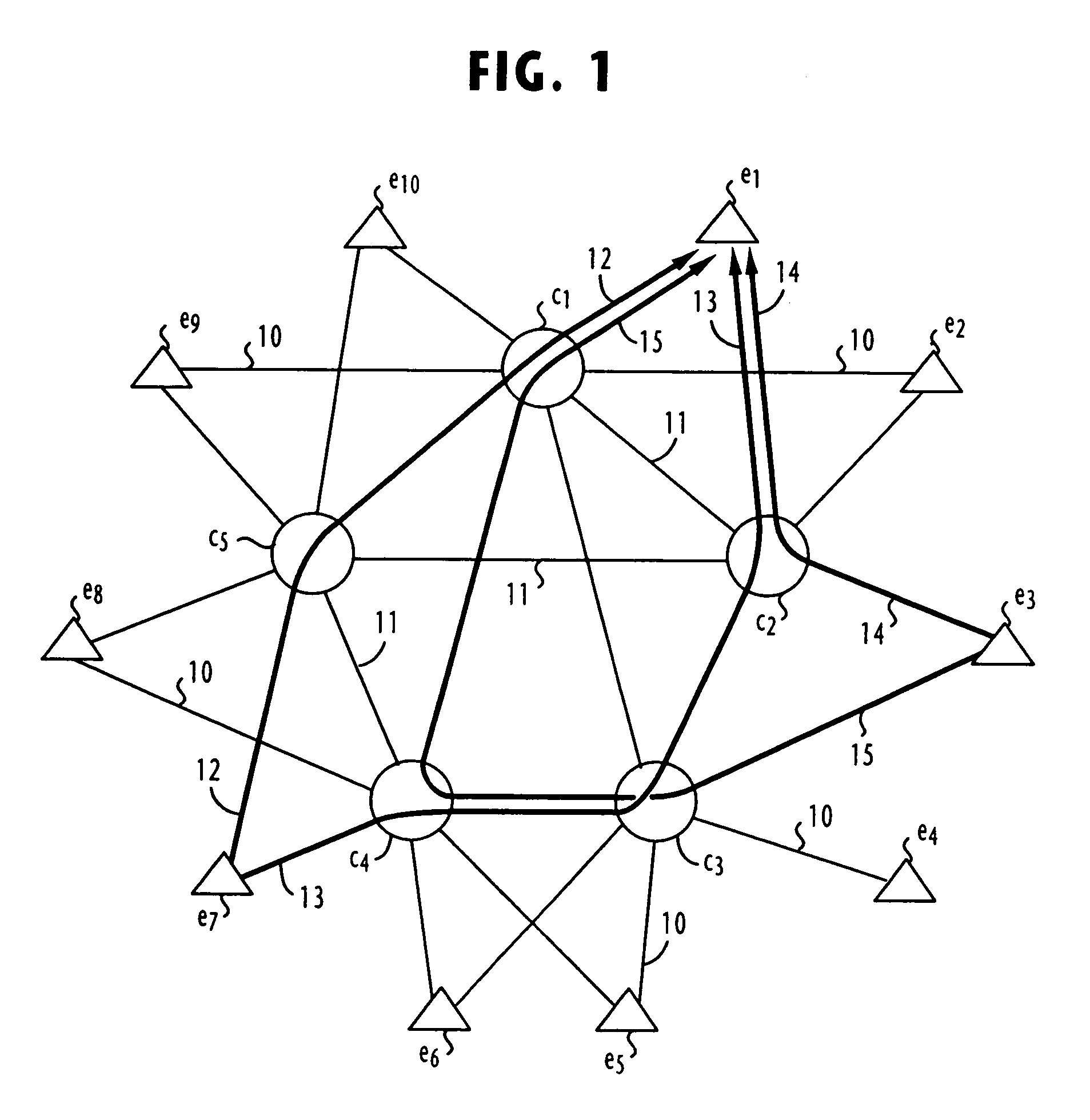
[0025]FIG. 1 represents a fault tolerant communication network in a directed graph for purposes of explanation of the present invention. As illustrated, the network comprises a plurality of edge nodes e1˜e10 and a plurality of core (intermediate) nodes c1˜c5. Each edge node is called an ingress node if it receives incoming traffic from end user systems or an egress node if it delivers outgoing traffic to end user systems. Edge nodes e1 ˜e10 are connected to adjacent core nodes as indicated by thin lines 10. Each of the core nodes c1˜c5 is connected to every other core nodes as indicated by a thin line 11.

[0026]As opposed to the usual tree graph representation in which the root node is connected by directed arcs (links) to the remaining nodes, the egress node is taken as a root node in the present invention and the links are directed towards the root (egress) node, rather than towards the remaining nodes. A link from one node to any of the other nodes is denoted by an ordered pair of...


PUM


Abstract

According to a first aspect of the present invention, an objective function is defined for minimizing a number of candidate tree graphs for accommodating the communication paths and a first constraint equation is defined for causing all of the candidate tree graphs to form a tree. A second constraint equation is defined for accommodating the communication paths in one of the candidate tree graphs. A third constraint equation is defined for determining whether each of the candidate tree graphs is used to accommodate the communication paths. A mathematical programming problem formed by the objective function, and the first, second and third constraint equations is solved to obtain a plurality of trees in which the communication paths can be accommodated.

Description

BACKGROUND OF THE INVENTION[0001]1. Field of the Invention[0002]The present invention relates generally to communication networks and more particularly to the design of communication paths of tree structure within a communication network between an ingress node and an egress node the network.[0003]2. Description of the Related Art[0004]In a label-switched communication system, such as ATM (asynchronous transfer mode) and MPLS (multiprotocol label switching) systems, an active communication path is provisioned between an ingress node and an egress node for carrying normal traffic and, in most cases, one or more spare paths are provisioned for purposes of protection switching or distributing overflow traffic. However, a large number of virtual channel identifiers (VCIs) and virtual path identifiers (VPIs) must be registered if all possible routes are provisioned between all pairs of ingress and egress nodes. In order to overcome this problem, a technique known “VP / VC merge” has been p...

Claims


Application Information

Patent Timeline
IPC IPC(8): H04L12/66G06F17/50H04L12/44H04L12/701H04L12/753
CPCH04L45/02H04L45/48H04L12/5601H04L2012/5685H04L2012/561H04L2012/562H04L45/484
Inventor SAITO, HIROYUKI
Owner NEC CORP
Why Eureka
Try Eureka