Image pickup apparatus with focusing lens control device
a control device and image technology, applied in the field of image pickup apparatus, can solve the problems of inability to maintain the in-focus state, the user's cost of video camera using such a microcomputer, and the cost of locus tracing method, so as to achieve comfortable and superior zooming performance. the effect of inexpensively
- Summary
- Abstract
- Description
- Claims
- Application Information
AI Technical Summary
Benefits of technology
Problems solved by technology
Method used
Image
Examples
first embodiment
[0102](First Embodiment)
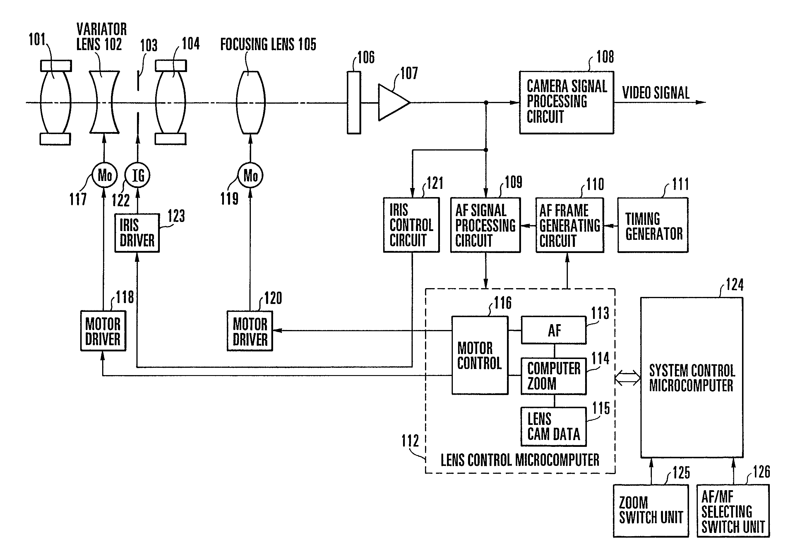
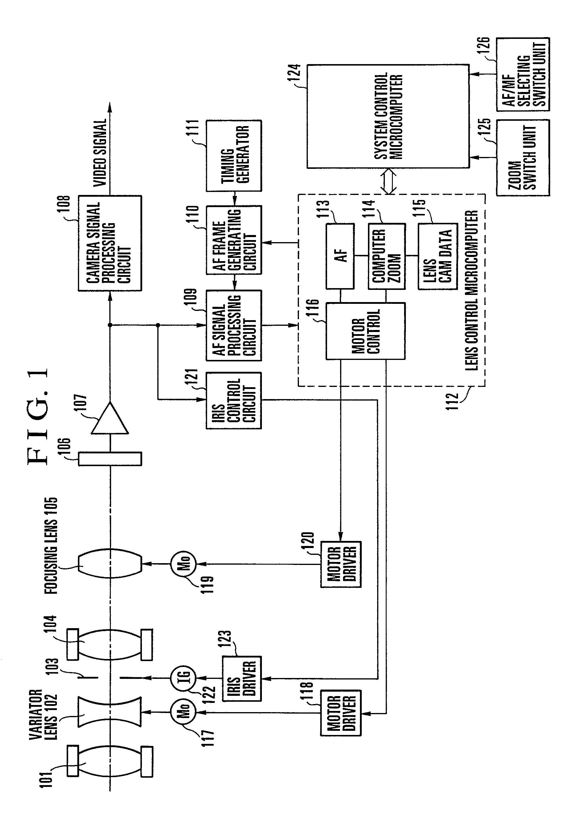
[0103]FIG. 1 is a block diagram showing the entire arrangement of a first embodiment of the present invention. The arrangement shown in FIG. 1 includes a fixed front lens group 101, a second lens group (variator lens) 102 for performing a magnification varying operation, an iris 103, a fixed third lens group 104, and a fourth lens group (focusing lens) 105 which has both a compensation function and a focusing function. These constituent elements 101 to 105 constitute an inner focus type of lens system. Image light which has passed through this lens system is focused on an image pickup surface of an image pickup element 106 and converted into a video signal by photoelectric conversion. The video signal is amplified to an optimum level by an amplifier 107, and the amplified video signal is inputted to a camera signal processing circuit 108 and converted into a standard television signal (video signal).
[0104]The video signal amplified by the amplifier 107 is sen...
second embodiment
[0136](Second Embodiment)
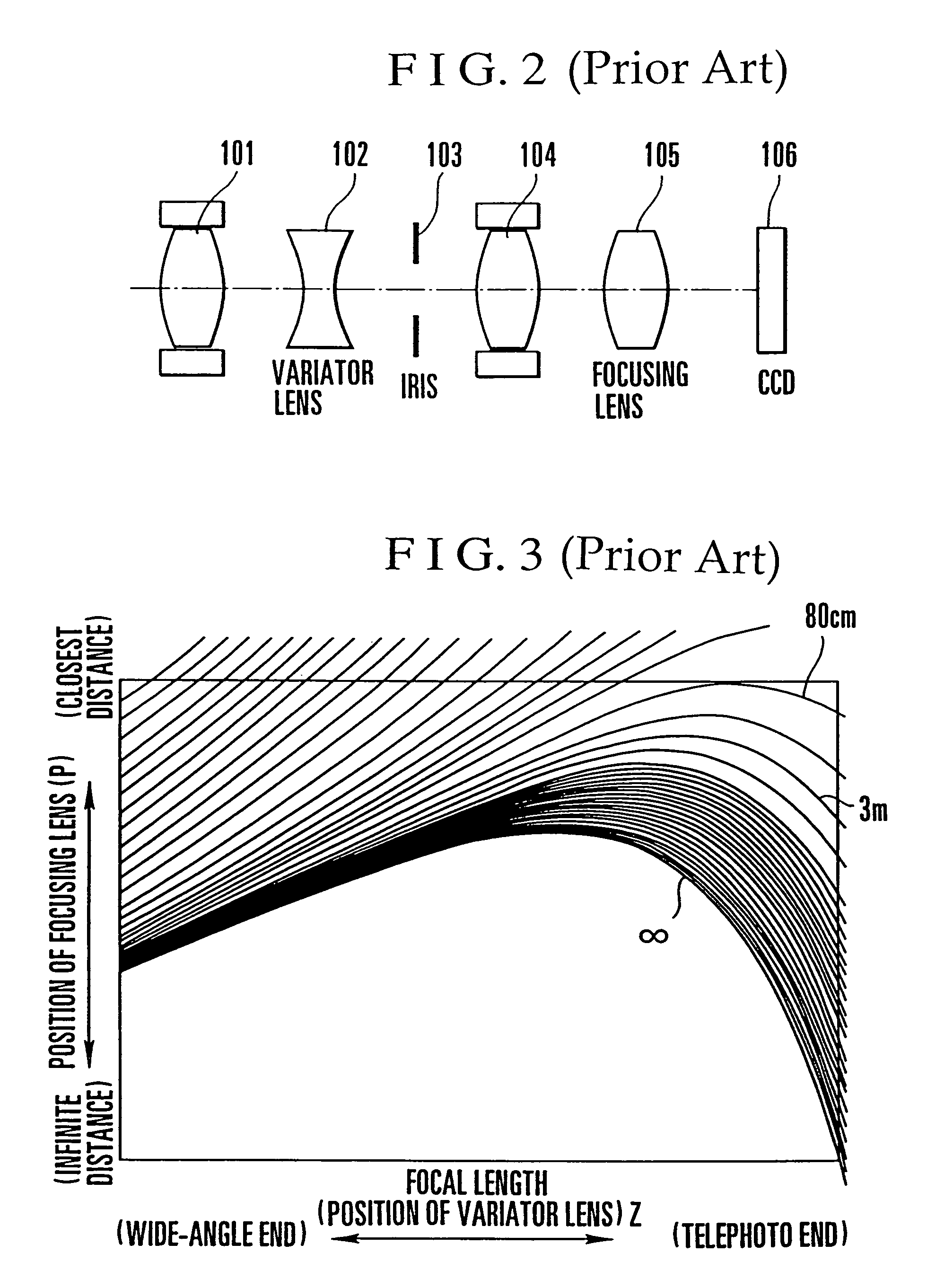
[0137]In the description of the first embodiment, reference has been made to the tracing method of accurately tracing a cam locus while reducing the load on a microcomputer. Even during a manual mode in which an in-focus cam locus to be traced is previously identified or even during an AF mode, as long as zooming is effected from a telephoto side toward a wide-angle side, the tracing method of the first embodiment does not give rise to defocusing. However, during zooming from the wide-angle side toward the telephoto side in the AF mode, since the variator lens moves in the direction in which in-focus cam loci gradually diverge from a point of convergence as described previously, defocusing will occur if a zooming operation is not performed while an in-focus cam locus is being identified. To solve the above problem, in accordance with the second embodiment which will be described below, there is provided an extended version of the first embodiment which can p...
third embodiment
[0151](Third Embodiment)
[0152]Although each of the above-described first and second embodiments uses a stepping motor as an actuator for driving a focusing lens, a third embodiment which will be described below uses a linear motor which features low drive noise, small drive vibration and superior high-speed driving performance.
[0153]First of all, the merit of using such linear motor as the focusing motor 119 for driving the focusing lens 105 (refer to FIG. 1) will be described. In a camera provided with an inner focus type of lens, if its focusing lens needs to keep maintaining an in-focus state while its variator lens is being moved at a uniform speed, it is necessary to increase the moving speed of the focusing lens near the telephoto end at which the slope of a cam locus becomes sharp. However, if a stepping motor is used as a focusing motor in the camera, the speed of the stepping motor which is required for increasing the moving speed of the focusing lens near the telephoto end...
PUM
 Abstract
Description
Claims
Application Information
 - R&D
- Intellectual Property
- Life Sciences
- Materials
- Tech Scout
- Unparalleled Data Quality
- Higher Quality Content
- 60% Fewer Hallucinations
Browse by: Latest US Patents, China's latest patents, Technical Efficacy Thesaurus, Application Domain, Technology Topic, Popular Technical Reports.
© 2025 PatSnap. All rights reserved.Legal|Privacy policy|Modern Slavery Act Transparency Statement|Sitemap|About US| Contact US: help@patsnap.com


