
Vehicle imaging system

a technology for imaging systems and vehicles, applied in the field of vehicles, can solve the problem that the driver cannot clearly see the hitch of the trailer, and achieve the effect of low cos

Inactive Publication Date: 2006-02-28
MAGNA ELECTRONICS
View PDF66 Cites 758 Cited by
  • Summary
  • Abstract
  • Description
  • Claims
  • Application Information

AI Technical Summary

Benefits of technology

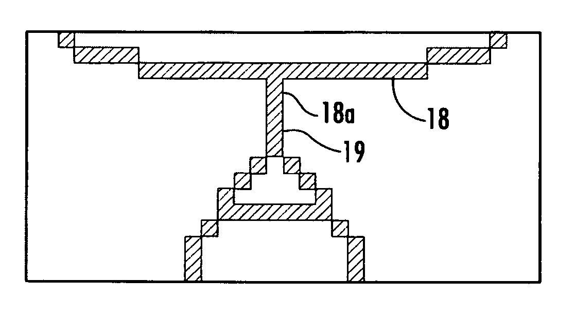
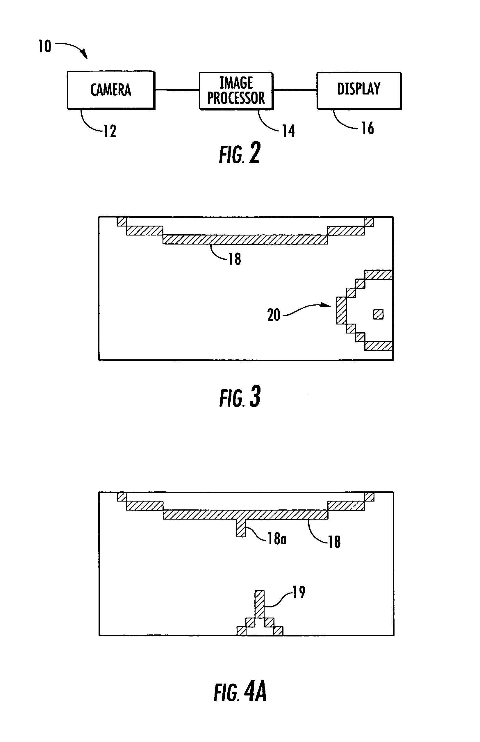
[0004]The present invention is intended to provide a low cost backup or reverse aid for a vehicle. The reverse aid provides a dot matrix type display which displays a simplified or iconistic representation of a vehicle bumper and / or other portion of the vehicle and any objects detected exteriorly of the vehicle. The present invention is also intended to provide a bracket for mounting an imaging sensor at an exterior or rearward portion of a vehicle in a manner which is not intrusive to the exterior or rearward portion of the vehicle.

Problems solved by technology

In such operations, the driver cannot clearly view the hitch of the trailer as the vehicle is backing up.

Method used


Image

  • Vehicle imaging system
  • Vehicle imaging system
  • Vehicle imaging system

Examples


Embodiment Construction

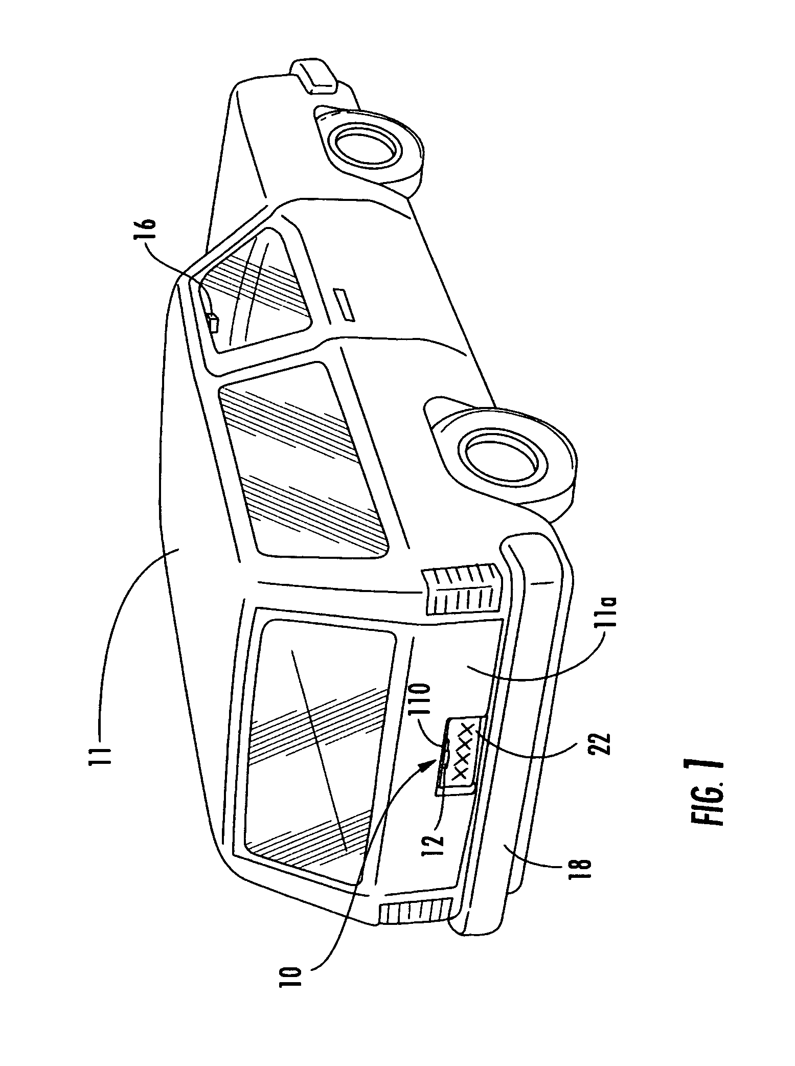
[0025]Referring now to the drawings and the illustrative embodiments depicted therein, a vehicle imaging system 10 includes an image sensor or camera 12, an image processing system or image processor 14 and a display 16 (FIGS. 1 and 2). The image processing system 14 receives an input or signal from a single camera or multiple cameras positioned at a portion of a vehicle 11, such as at an exterior portion of the vehicle, such as at a rearward exterior portion 11a of the vehicle 11. The camera 12 is operable to capture an image of a scene exteriorly, and preferably rearwardly, of the vehicle. The camera may be any known camera or image sensor, such as an imaging array sensor, such as a CMOS sensor or CCD sensor, such as described in commonly assigned U.S. Pat. Nos. 5,550,677; 6,097,023 and 5,796,094, which are hereby incorporated herein by reference. The image processing system is operable to process the image or signal received from the camera. The display is then operable to displa...


PUM


Abstract

A vehicle imaging system includes an imaging sensor having a field of view exterior of a vehicle, an image processor and a display. The imaging sensor generates a signal indicative of an image representative of a scene occurring within the field of view. The image processor receives the signal from the imaging sensor and processes the signal to detect at least one relevant object within the image. The display is operable to display at least one iconistic representation of the at least one detected relevant object in response to an output signal generated by the image processor. The display is positionable within the vehicle and is viewable by a driver or passenger or occupant of the vehicle. The imaging sensor may be mounted to a mounting bracket mounted at a license plate area of the vehicle.

Description

CROSS REFERENCE TO RELATED APPLICATIONS[0001]The present application claims priority of U.S. provisional applications, Ser. No. 60 / 373,932, filed Apr. 19, 2002 by McMahon for VEHICLE IMAGING SYSTEM and Ser. No. 60 / 376,508, filed Apr. 30, 2002 by Bingle for VEHICLE LICENSE PLATE BRACKET which are hereby incorporated herein by reference in their entireties.FIELD OF THE INVENTION[0002]The present invention relates to a vehicle imaging system and, more particularly, to a vehicle imaging system useful for a backup or reverse aid to the driver of a vehicle. The present invention is also related to a bracket for mounting an imaging sensor at an exterior portion, such as a rearward portion, of a vehicle.BACKGROUND OF THE INVENTION[0003]It is known to provide an imaging system for a vehicle which functions to provide a rearward view of the vehicle to a driver via a display within the vehicle. Such systems function to assist a driver in backing up a vehicle to a trailer or otherwise positioni...

Claims


Application Information

Patent Timeline
Patent Type & Authority Patents(United States)
IPC IPC(8): B60Q1/00B60Q1/48B60R1/00
CPCB60Q9/005B60R1/00B60R2300/8066B60R2300/30B60R11/04B60R1/26
Inventor MCMAHON, MARTHA A.BINGLE, ROBERT L.
Owner MAGNA ELECTRONICS
Learn More