
Pneumatic human power conversion system based on children's play

Inactive Publication Date: 2006-02-28
PANDIAN SHUNMUGHAM RAJASEKARA
View PDF32 Cites 62 Cited by
  • Summary
  • Abstract
  • Description
  • Claims
  • Application Information

AI Technical Summary

Benefits of technology

[0010]Compressed air energy storage and actuation have advantages of environment-friendliness and low-cost, and are being employed widely in applications ranging from children's toys to underground energy storage for peak-power demand. While compressed air systems have low energy efficiency, high-efficiency compressor systems have been developed for gasoline-pneumatic hybrid cars.
[0012]Several commercial products based on the human power conversion exist. Human power conversion has been used in pneumatic orthosis systems to reduce the need for large air reservoirs. It has also been proposed as a power source for emergency rescue situations such as earthquakes.
[0017]Compressed air devices are used for the conversion and storage of human power in the present invention, though electric generators can also be used for this purpose. The main reason for this is the hazards of electric shock and fire in the case of malfunction or accidents leaving open wires. Use of compressed air is explosion- and fire-proof and open tubing results simply in air leakage. The lower efficiency of the resulting system (due to pressure drop in pipelines and heat in pressurizing) is compensated by the simplicity, safety, and low-cost of operation of the pneumatic system.

Problems solved by technology

While individual human calorific consumption of 2500 kilocalories per day is equivalent to the energy stored in about 1050 AA batteries, harnessing this power individually results in expensive, mainly electrical, systems with low-power outputs, e.g., clockwork radio, hand-cranked lantern, etc.
While compressed air systems have low energy efficiency, high-efficiency compressor systems have been developed for gasoline-pneumatic hybrid cars.

Method used


Image

  • Pneumatic human power conversion system based on children's play
  • Pneumatic human power conversion system based on children's play
  • Pneumatic human power conversion system based on children's play

Examples


Embodiment Construction

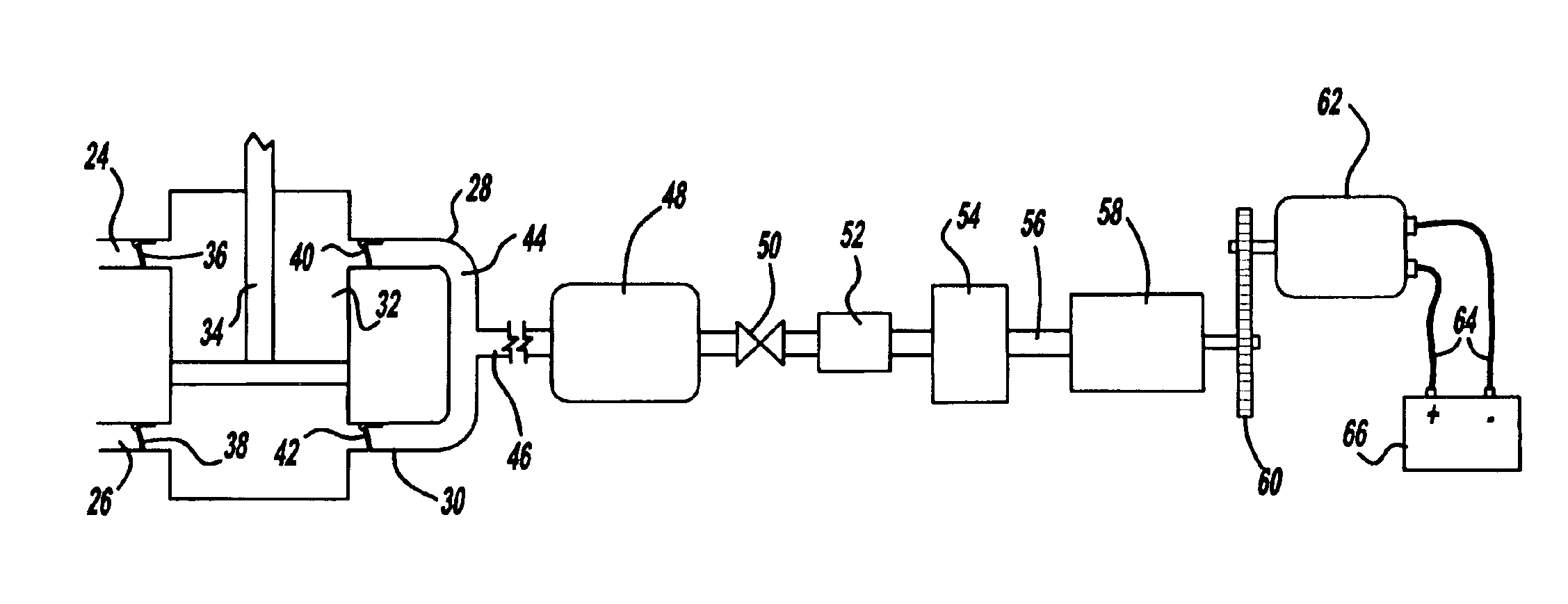
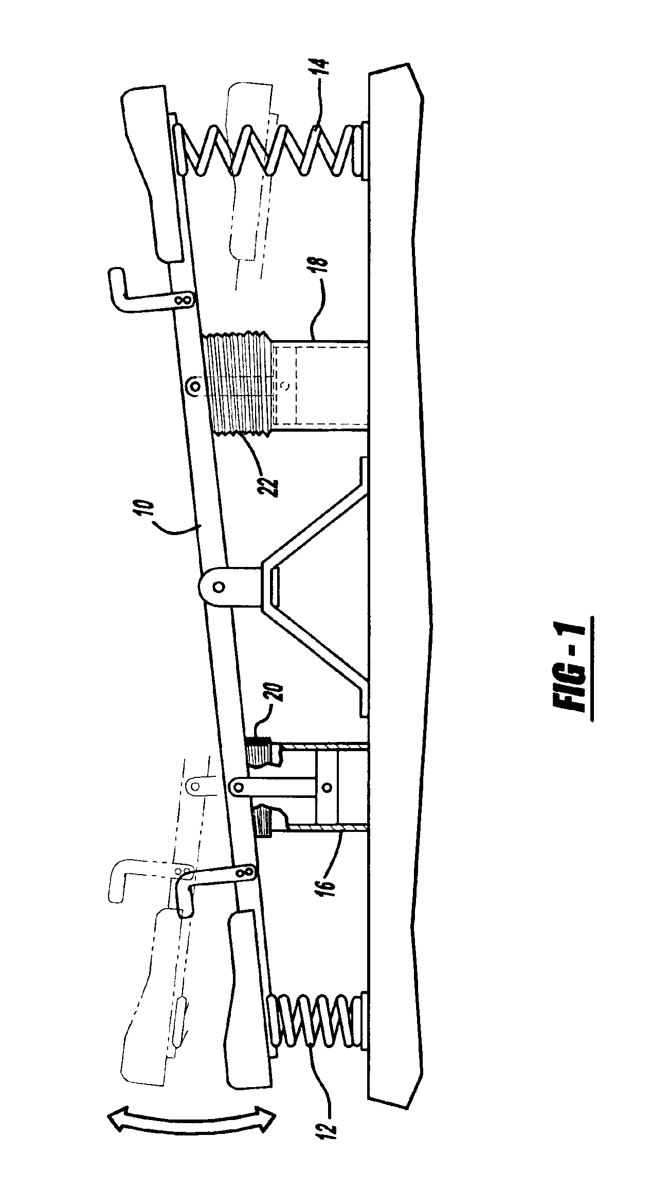
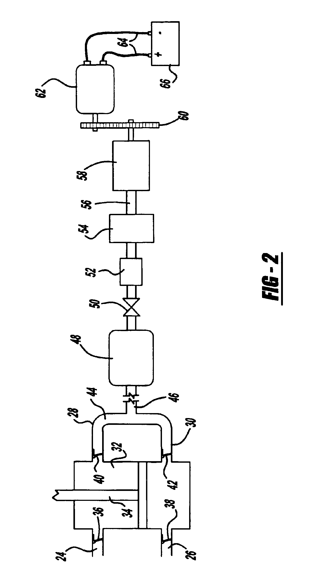
[0031]FIGS. 1 and 2 illustrate the basic principle of the new invention. For simplicity, we limit our discussion to power conversion based on a seesaw. The cases of a swing and a merry-go-around can be considered similarly.

[0032]In FIG. 1, the seesaw 10 is often supplied with hard cylindrical helical springs 12, 14 to smoothen the actions of the seesaw mechanism. In the present mechanism, instead of the springs we employ two pneumatic cylinders 16, 18 on the two sides of the seesaw. To prevent any accidents and injuries to players' limbs from the moving pistons, we provide a bellows-type flexible sheath between the bottom of seesaw and the top of the cylinder as shown 20, 22. The outer bodies of the cylinders would get heated due to the compression of air inside. This would require shielding of the outer bodies too (not shown here).

[0033]To simplify the system and make it portable, the bottom end of the cylinders can also be fixed to the central support of the seesaw, rather than be...


PUM


Abstract

When large numbers of children play in a playground, part of the power of their play could be usefully harnessed resulting in large energy storage. This stored energy can then be converted for basic, low-power, applications in the school such as lighting, communication, or operating fans. Energy can be produced through the use of pneumatic (i.e., compressed air) systems such as cylinders, motors, valves, and regulators for the conversion of human power of children's play in school playgrounds and other public places. The energy of the compressed air can then be converted to electricity for purposes such as lighting and communication. This provides a low-cost, low-resource means of generation of electricity, especially for use in developing countries.

Description

TECHNICAL FIELD[0001]The present invention is based on the use of pneumatic (i.e., compressed air) systems such as cylinders, motors, valves, and regulators for the conversion of human power of children's play in school playgrounds and other public places. The energy of the compressed air can then be converted to electricity for purposes such as lighting and communication. This provides a low-cost, low-resource means of generation of electricity, especially for use in developing countries.BACKGROUND OF THE INVENTION[0002]The current state-of-art inventions using human power are mainly based on harnessing human power at the individual level. Therefore, they are limited to producing low power output and are discontinuous. For example, rotating the crank of a clockwork radio for a few minutes produces enough power for the radio for about half hour or for several seconds of lighting.[0003]By contrast, the present invention is based on harnessing the collective energy of a number of chil...

Claims


Application Information

Patent Timeline
IPC IPC(8): A63B71/00F03G5/00F03G5/06
CPCF03G5/06F03G5/00F03G5/095F03G5/103F03G5/062F03G5/086
Inventor PANDIAN, SHUNMUGHAM RAJASEKARA
Owner PANDIAN SHUNMUGHAM RAJASEKARA
Learn More