
Methods and devices for spinal disc annulus reconstruction and repair

a technology of spinal disc and annulus, which is applied in the direction of prosthesis, ligaments, surgical staples, etc., can solve the problems of increased scar formation, increased inflammation surrounding the nerve, and continued back pain, so as to reduce the risk, increase the integrity of the repair, and promote healing

Inactive Publication Date: 2006-02-28
KRT INVESTORS
View PDF147 Cites 309 Cited by
  • Summary
  • Abstract
  • Description
  • Claims
  • Application Information

AI Technical Summary

Benefits of technology

[0019]Another advantage of the present invention over the prior art in utilizing the inner surface of the annulus is the reduction of the risk of having a portion of the device protruding from the exterior surface of the annulus. Device materials protruding from the exterior of the annulus pose a risk of damaging the nerve root and / or spinal canal which are in close proximity. Damage to these structures can result in continued pain, incontinence, bowel dysfunction and paralysis.
[0020]The present invention incorporates the concept of pulling the tissues together that surround the aperture, the inner surface, and the outer surface of the annulus to help close the aperture, increase the integrity of the repair, and promote healing.
[0021]An example of the technique and placement of the device according to one embodiment of the invention is as follows:
[0022]1. An aperture is created measuring approximately, for example, 6 mm×2 mm in the wall of the annulus after performing a discectomy procedure in which a portion of the nucleus is also removed from the disc space, as shown in FIGS. 32a, 32b, 33a and 33b.
[0023]2. Two or more sutures are passed through the upper and lower surfaces of the aperture and they are pushed within the intervertebral disc space to create a “sling” to receive the fascial autograft as shown for example in FIG. 34.
[0024]3. A piece of para-spinal fascial tissue is removed from the patient measuring approximately, for example, 10 mm×5 mm.

Problems solved by technology

The nuclear material of the disc is toxic to the nerves and is believed to cause increased inflammation surrounding the nerves, which in turn can cause increased scar formation (adhesions or epidural fibrosis) upon healing.
Adhesions created around the nerve roots can cause continued back pain.

Method used


Image

  • Methods and devices for spinal disc annulus reconstruction and repair
  • Methods and devices for spinal disc annulus reconstruction and repair
  • Methods and devices for spinal disc annulus reconstruction and repair

Examples


Embodiment Construction

[0109]Reference will now be made in detail to selected illustrative embodiments of the invention, with occasional reference to the accompanying drawings. Wherever possible, the same reference numbers will be used throughout the drawings to refer to the same or like parts.

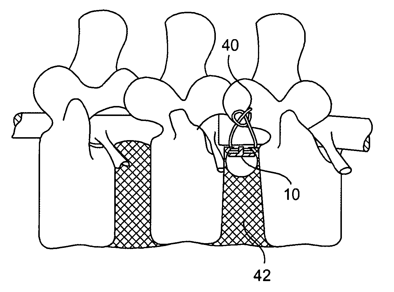
[0110]In one embodiment of the present invention, as shown in FIG. 7, a damaged annulus 42 is repaired by use of surgical sutures 40. One or more surgical sutures 40 are placed at about equal distances along the sides of a pathologic aperture 44 in the annulus 42. Reapproximation or closure of the aperture 44 is accomplished by tying the sutures 40 so that the sides of the aperture 44 are drawn together. The reapproximation or closure of the aperture 44 enhances the natural healing and subsequent reconstruction by the natural tissue (e.g., fibroblasts) crossing the now surgically narrowed gap in the annulus 42. Preferably, the surgical sutures 40 are biodegradable, but permanent non-biodegradable may be utilized. In...


PUM

PropertyMeasurementUnit
Widthaaaaaaaaaa
Heightaaaaaaaaaa
Tensionaaaaaaaaaa

Abstract

The present invention provides methods and devices for annulus disc repair with and without the use of a patch or stent. The methods and devices are particularly suited to the repair and / or reconstruction of the spinal disc wall (annulus) after surgical invasion or pathologic rupture, with reduced failure rate as compared to conventional surgical procedures.

Description

CROSS-REFERENCE TO A RELATED APPLICATION[0001]This application is a continuation-in-part of U.S. patent application Ser. No. 09 / 947,078, filed Sep. 5, 2001, which is a continuation of U.S. patent application Ser. No. 09 / 484,706, filed Jan. 18, 2000, which claims the benefit of U.S. Provisional Application No. 60 / 160,710, filed Oct. 20, 1999. This application also claims the benefit of U.S. Provisional Application No. 60 / 309,105, filed Jul. 31, 2001. This application is also related to, and claims the benefit of, U.S. patent application Ser. No.10 / 075,615, filed on Feb. 15, 2002, and U.S. patent application Ser. No. 10 / 085,040, filed Mar. 1, 2002.FIELD OF THE INVENTION[0002]The invention generally relates to methods and implantable medical devices for the closure, sealing and / or repair of an aperture in the intervertebral disc annulus. The term “aperture” refers to a hole in the annulus that is a result of a surgical incision into the intervertebral disc annulus, or the consequence o...

Claims


Application Information

Patent Timeline
IPC IPC(8): A61F2/44A61B17/56A61B17/00A61B17/04A61B17/06A61B17/064A61B17/70A61B17/86A61B17/88A61FA61F2/00A61F2/02A61F2/08A61F2/28A61F2/30A61F2/46A61L17/06A61L31/02
CPCA61F2/441A61F2/442A61F2/4611A61B17/04A61F2310/00011A61B17/0642A61B17/1155A61B2017/00004A61B2017/0409A61B2017/0417A61B2017/0472A61B2017/06052A61B2017/06176A61B2017/0641A61B2017/0647A61B2017/0648A61F2/0063A61F2/30907A61F2/4601A61F2002/0072A61F2002/2817A61F2002/30062A61F2002/30093A61F2002/30158A61F2002/30299A61F2002/30579A61F2002/30777A61F2002/30784A61F2002/30841A61F2002/4435A61F2002/444A61F2002/4627A61F2210/0004A61F2210/0019A61F2230/0026A61F2230/0093A61B17/06166A61F2002/30092
Inventor CAUTHEN III, JOSEPH C.BURNS, MATTHEW M.WALES, LAWRENCE W.DUKART, BRIAN L.WESSMAN, BRADLEY J.HOUFBURG, RODNEY L.BURMEISTER, PAUL
Owner KRT INVESTORS
Learn More