
Network connector module

a technology of network connectors and connector modules, applied in the direction of coupling devices, two-part coupling devices, printed circuits, etc., can solve the problems of insufficient service of network established with only a few computers, assembly problems, and the inability of rj-45 connector modules to be smoothly installed on the circuit board, so as to reduce the quantity of pins, improve manufacturing quality and product yield, and reduce the effect of quantity

Inactive Publication Date: 2006-02-28
DELTA ELECTRONICS INC
View PDF6 Cites 52 Cited by
  • Summary
  • Abstract
  • Description
  • Claims
  • Application Information

AI Technical Summary

Benefits of technology

[0008]One object of the present invention is to provide a network connector module to move some pins from a base of the network connector module to an upper shell thereof to reduce the quantity of pins directly coupling to the circuit board so as to make assembly more convenient.
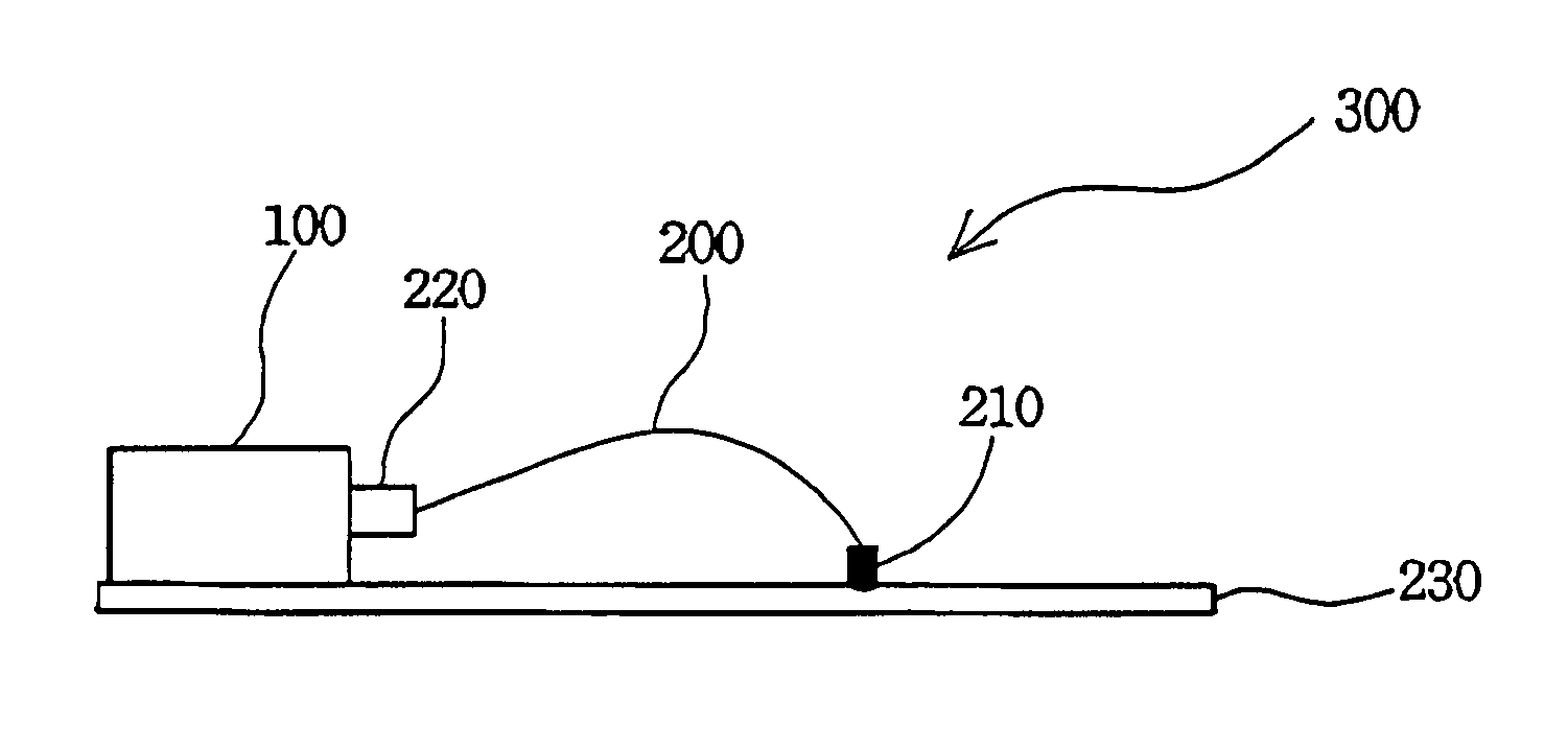
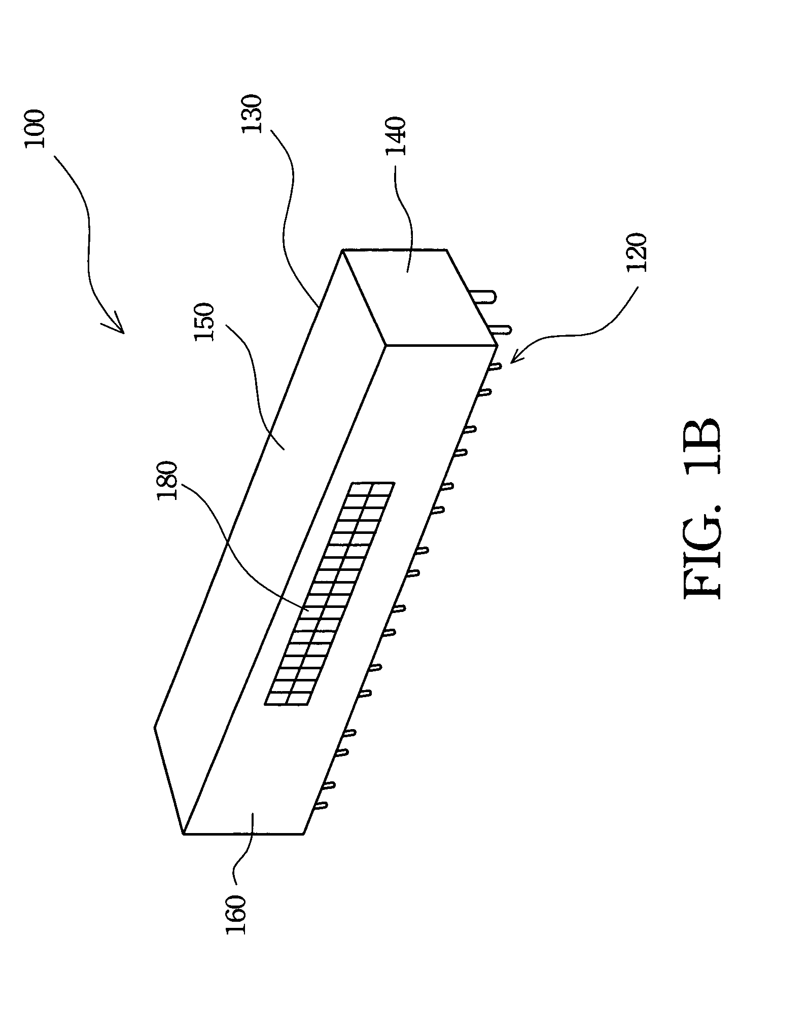
[0009]Another object of the present invention is to provide a network connector module with a second connector to move pins for transmitting power from a base of the network connector module to an upper shell thereof and use a power cord to couple the second connector to the circuit board for reducing the quantity of pins directly coupling to the circuit board. The pins for transmitting power and the pins for transmitting signals are thus efficiently separated to enhance the signal quality.
[0010]The present invention provides a network connector module. The network connector module utilizes a separation of pins for transmitting signals and pins for transmitting power to reduce the signal distortion due to interference from power pins. The network connector module has a plurality of phone jacks, a plurality of pins, and a second connector. The pins connect with the phone jacks and electrically couple to a circuit board for transmitting signals. The second connector configured on an upper shell of the network connector module is utilized to transmit power with a power cord.
[0012]The network connector module according to the present invention utilizes the second connector to separate the pins for transmitting power and signals, and reduces the quantity of the pins on the base of the network connector module. An electrical equipment with the network connector module can be more easily and smoothly assembled. Therefore, the manufacture quality and product yield can be enhanced. Furthermore, because the second connector can efficiently enlarge the safety distance between the pins for transmitting power and signals, the signal transmission quality is also enhanced.

Problems solved by technology

Therefore, a network established with only a few computers provides insufficient service.
Because the RJ-45 connector module has too many pins, an assembly problem is therefore caused.
If even one pin is not aligned to the corresponding contact hole, the RJ-45 connector module cannot be smoothly installed on the circuit board.
Furthermore, the signals thereof may interfere with each other because many pins are too close, especially when a power pin is too close to a signal pin.

Method used


Image

  • Network connector module
  • Network connector module
  • Network connector module

Examples


Embodiment Construction

[0017]The following description is of the best presently contemplated mode of carrying out the present invention. This description is not to be taken in a limiting sense but is made merely for the purpose of describing the general principles of the invention. The scope of the invention should be determined by referencing the appended claims.

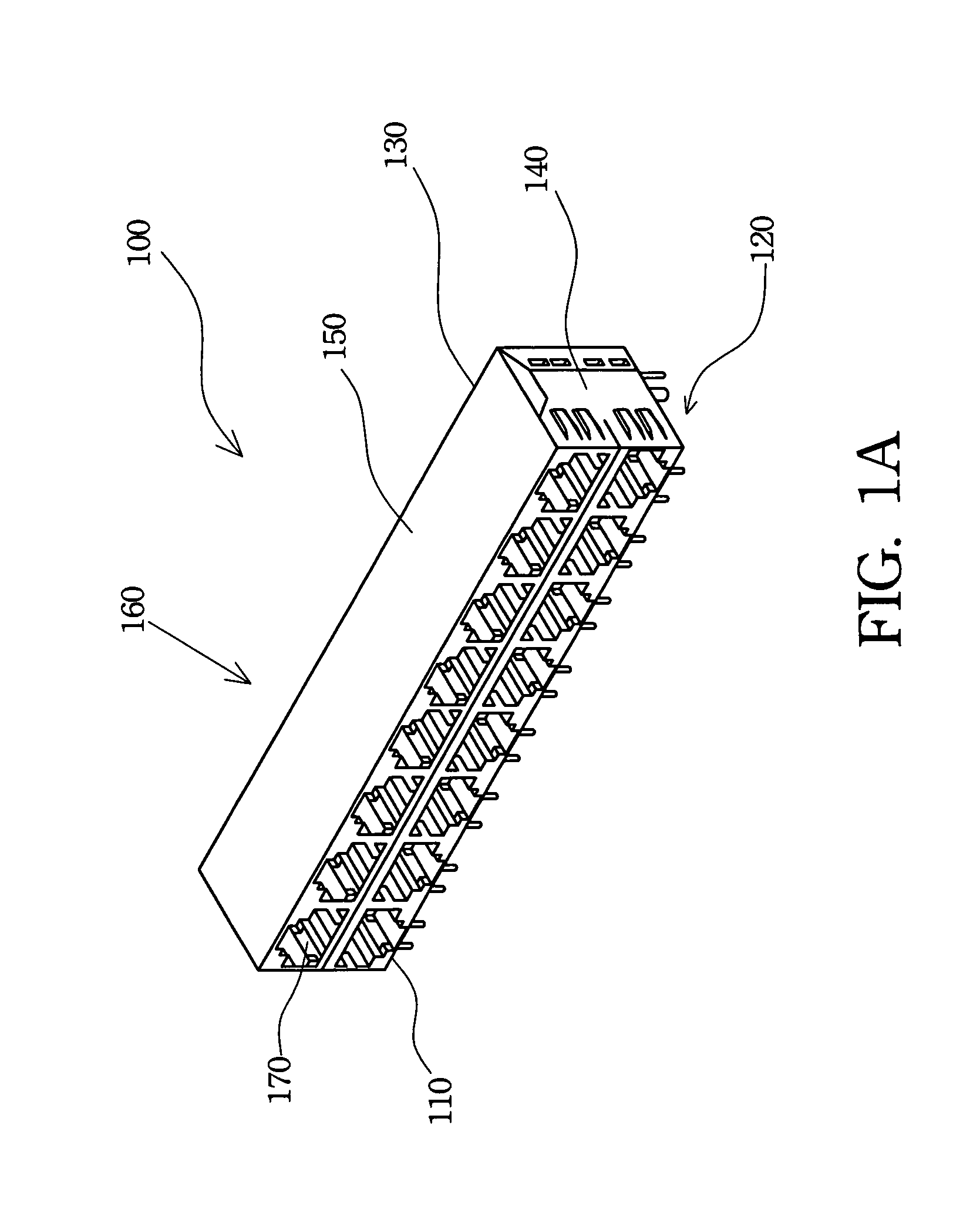
[0018]FIG. 1A is a schematic view of a network connector module according to the present invention. The network connector module 100 has a base 110, an upper shell 130, a plurality of phone jacks, e.g. RJ-45 phone jacks 170, and a plurality of pins 120. The RJ-45 phone jack 170 is utilized to couple to a RJ-45 phone plug for transmitting signals and supplying power for an electrical network equipment with a power over ethernet (POE) technology.

[0019]Because the network connector module 100 has a plurality of RJ-45 phone jack 170, the pins 120 thereof are increased. However, a conventional RJ-45 connector modules has too many pins to transmit sign...


PUM


Abstract

A network connector module is described. The network connector module keeps a safe distance between signal pins and power pins to improve a signal transmission quality thereof. The network connector module includes a plurality of phone jacks, a plurality of pins and a second connector. The pins electrically couple to a circuit board to transmit signals. The second connector is fixed on an upper shell of the network connector module and utilizes a power cord to couple to the circuit board for transmitting power.

Description

FIELD OF THE INVENTION[0001]The present invention relates to a network connector module and, in particular, to a power over ethernet (POE) network connector module.BACKGROUND OF THE INVENTION[0002]Information technology and the network industry are highly developed now. People utilize networks to search for information and provide services. Hence, the growing network provides humans with a comfortable and fast information search environment.[0003]At this time, there is a lot of information to be distributed over the network. Therefore, a network established with only a few computers provides insufficient service. Network systems are established with more computers and the computer apparatuses may even be distributed in different places all over the world. The computer apparatuses, such as workstations, servers, database memory, routers, and backup devices, connect with each other via the network. Nowadays, almost every personal computer provides an interface to access the network, a...

Claims


Application Information

Patent Timeline
Patent Type & Authority Patents(United States)
IPC IPC(8): H01R12/00H01R12/16H01R13/717H01R13/719
CPCH01R24/64H01R13/717H01R13/719H01R13/7175
Inventor HSU, HAN-CHENGCHEN, CHIH-TSEKAO, CHING-MANSHIEH, YEOU-JEN
Owner DELTA ELECTRONICS INC
Learn More