
Reciprocating refrigerant compressor

a refrigerant compressor and compressor technology, applied in the direction of machines/engines, liquid fuel engines, positive displacement liquid engines, etc., can solve the problem of applying excessive load, and achieve the effect of preventing timing delay

Inactive Publication Date: 2006-02-28
ZEXEL VALEO CLIMATE CONTROL CORP SAITAMA
View PDF29 Cites 18 Cited by
  • Summary
  • Abstract
  • Description
  • Claims
  • Application Information

AI Technical Summary

Benefits of technology

[0019]For example, when liquid is compressed within a compression chamber, excessive load is applied during the compression stroke to an inlet valve whereby the inlet valve is about to be largely bent toward the suction chamber side. However, the inlet valve is supported by the ribs, which restricts excessive bend of the inlet valve. Therefore, even when the area of the inlet port is increased, it is possible to prevent leakage of liquid refrigerant into the suction chamber side, and deformation and breakage of the inlet valve.
[0023]Since the ribs have a surface formed with a groove or a hole, as described above, lubricating oil collected between the inlet valve and the valve plate is discharged via the grooves or the holes. Therefore, it is possible to prevent delay of timing in which the inlet valve opens during the suction stroke.

Problems solved by technology

For example, when liquid is compressed within a compression chamber, excessive load is applied during the compression stroke to an inlet valve whereby the inlet valve is about to be largely bent toward the suction chamber side.
However, the inlet valve is supported by the ribs, which restricts excessive bend of the inlet valve.

Method used


Image

  • Reciprocating refrigerant compressor
  • Reciprocating refrigerant compressor
  • Reciprocating refrigerant compressor

Examples


first embodiment

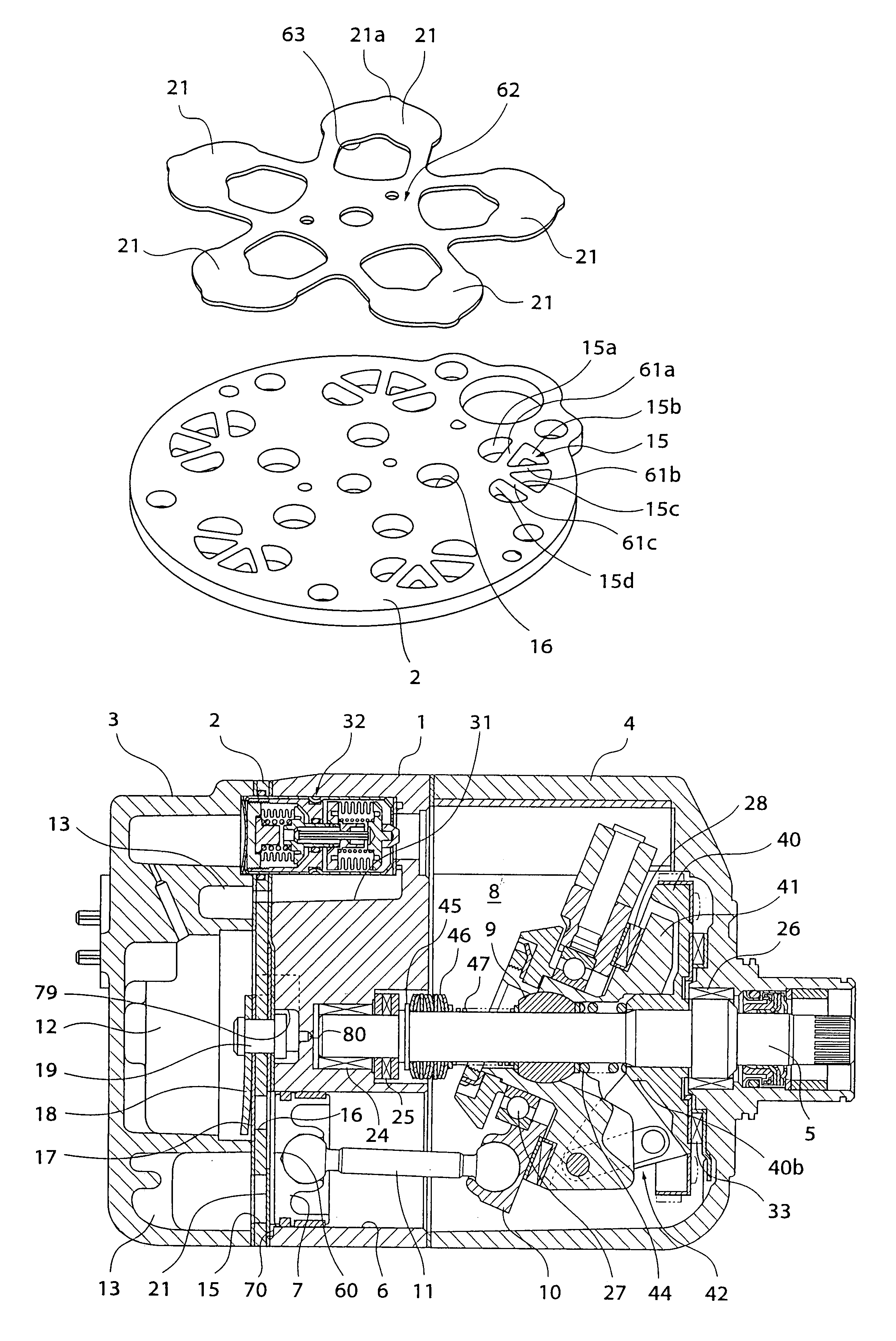
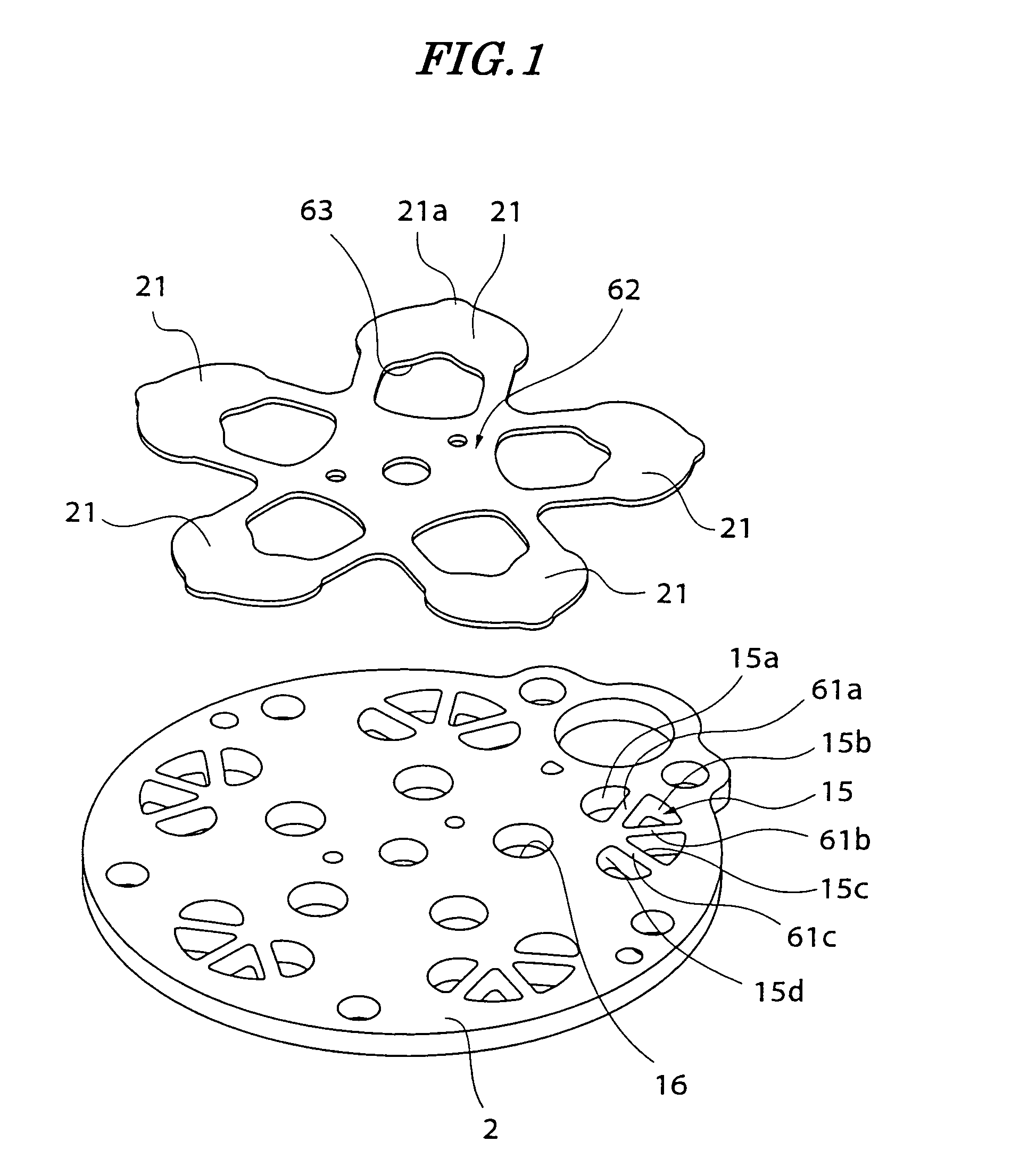
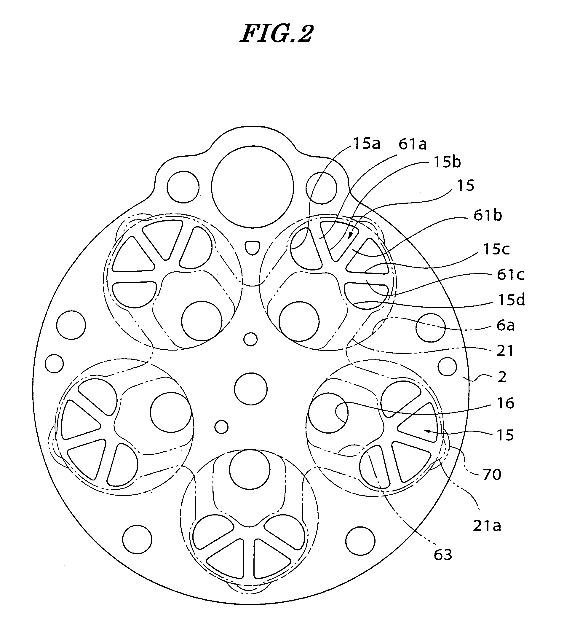
[0038]FIG. 4 is a longitudinal cross-sectional view of a wobble plate compressor according to the invention. FIG. 1 is a perspective view showing a valve plate and a valve sheet of the wobble plate compressor. FIG. 2 is a plan view of the valve plate shown in FIG. 1, and FIG. 3 is a fragmentary enlarged view of the valve plate shown in FIG. 2.

[0039]This compressor has a cylinder block 1 having one nd thereof secured to a rear head (cylinder head) 3 via a valve plate 2 and the other end thereof secured to a front head 4.

[0040]The cylinder block 1 has a plurality of cylinder bores 6 axially extending therethrough at predetermined circumferential intervals about the shaft 5. Each cylinder bore 6 has a piston 7 slidably received therein. The cylinder bore 6 defines a compression chamber 60 therein, the volume of which is changed with motion of the piston 7. An opening edge 6a of the cylinder bore 6 is formed with a stopper recess 70, at a location opposed to an end portion 21a of an inl...

third embodiment

[0055]In the suction stroke, as the piston 7 moves to the bottom dead center position, the difference between pressure in the compression chamber 60 and pressure in the suction chamber 13 is increased, so that the inlet valve 21 is bent into the compression chamber 60 to open the inlet port 15, via which the refrigerant gas in the suction chamber 13 is drawn into the compression chamber 60. As described above, the five inlet ports 15 are each comprised of a plurality of holes 15a to 15d, and the sum total of the respective areas of the holes 15a to 15d is larger than the area of the inlet port 715 of the prior art, which makes the suction efficiency higher than the prior art to improve the performance of the refrigerant compressor. Further, the flow of refrigerant gas drawn in is rectified (this is also the case with the invention).

[0056]Further, in the compression stroke, as the piston 7 moves to the top dead center position, the volume of the compression chamber 60 is progressivel...


PUM


Abstract

An inlet port 15 is divided into a plurality of holes 15a, 15b, 15c, 15 by ribs 61a, 61b, 61c. For example, when liquid refrigerant is compressed within a compression chamber, the inlet valve 21 receives excessive load which is about to bend the inlet valve 21 largely toward the suction chamber side. However, the inlet valve 21 is supported by the ribs 61a, 61b, 61c, and therefore the inlet valve 21 is hardly bent, but the inlet port 21 is positively closed.

Description

TECHNICAL FIELD[0001]This invention relates to a reciprocating refrigerant compressor used as a refrigerant compressor for an automotive air conditioner, and more particularly to a reciprocating refrigerant compressor of a type in which pistons reciprocate, such as a wobble plate compressor and a swash plate compressor.BACKGROUND ART[0002]A wobble plate compressor includes a cylinder block having a plurality of cylinder bores, a plurality of pistons for reciprocating within the respective cylinder bores, a cylinder head secured to an end face of the cylinder block via a valve plate, and a plurality of inlet valves for opening and closing a plurality of inlet ports formed through the valve plate.[0003]Within the cylinders are formed compression chambers, respectively, and the volume of each compression chamber varies with the motion of a piston associated therewith.[0004]The cylinder head has a suction chamber formed therein for receiving low-pressure refrigerant gas flowing therein ...

Claims


Application Information

Patent Timeline
Patent Type & Authority Patents(United States)
IPC IPC(8): F04B39/10F04B53/10F04B27/10
CPCF04B39/108F04B27/1009Y10T137/784
Inventor IZAWA, RYOSUKEKANAIZUKA, MINORUARAI, KATSUHIKOSAKAMOTO, KATSUMI
Owner ZEXEL VALEO CLIMATE CONTROL CORP SAITAMA
Learn More