Surface acoustic wave device with reflection electrodes having pitches that vary
a surface acoustic wave and reflection electrode technology, applied in piezoelectric/electrostrictive devices, device material selection, piezoelectric/electrostrictive devices, etc., can solve the problem of not disclosing a technique for improving and achieve the suppression of spurious signals and the shape factor, improve the sharpness of the cut-off region of the pass band, and improve the effect of spurious signals
- Summary
- Abstract
- Description
- Claims
- Application Information
AI Technical Summary
Benefits of technology
Problems solved by technology
Method used
Image

Examples
first embodiment
(First Embodiment)
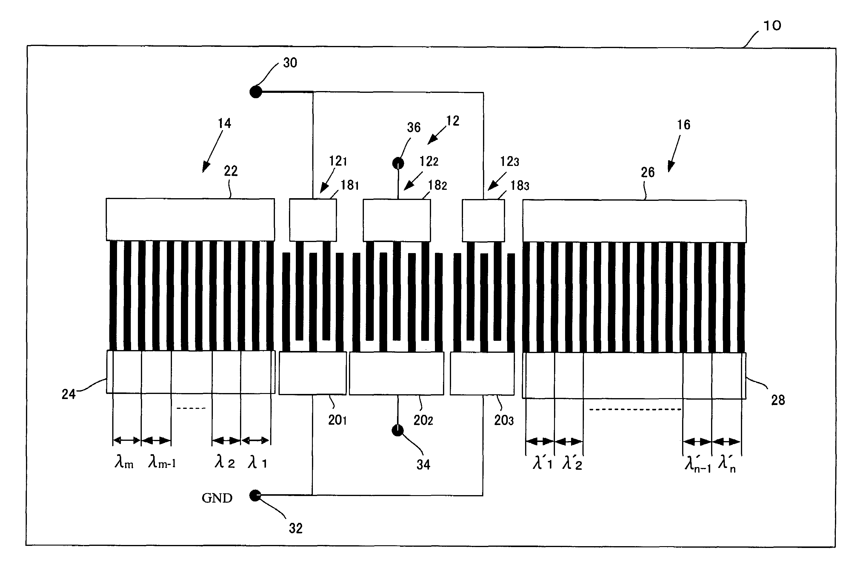
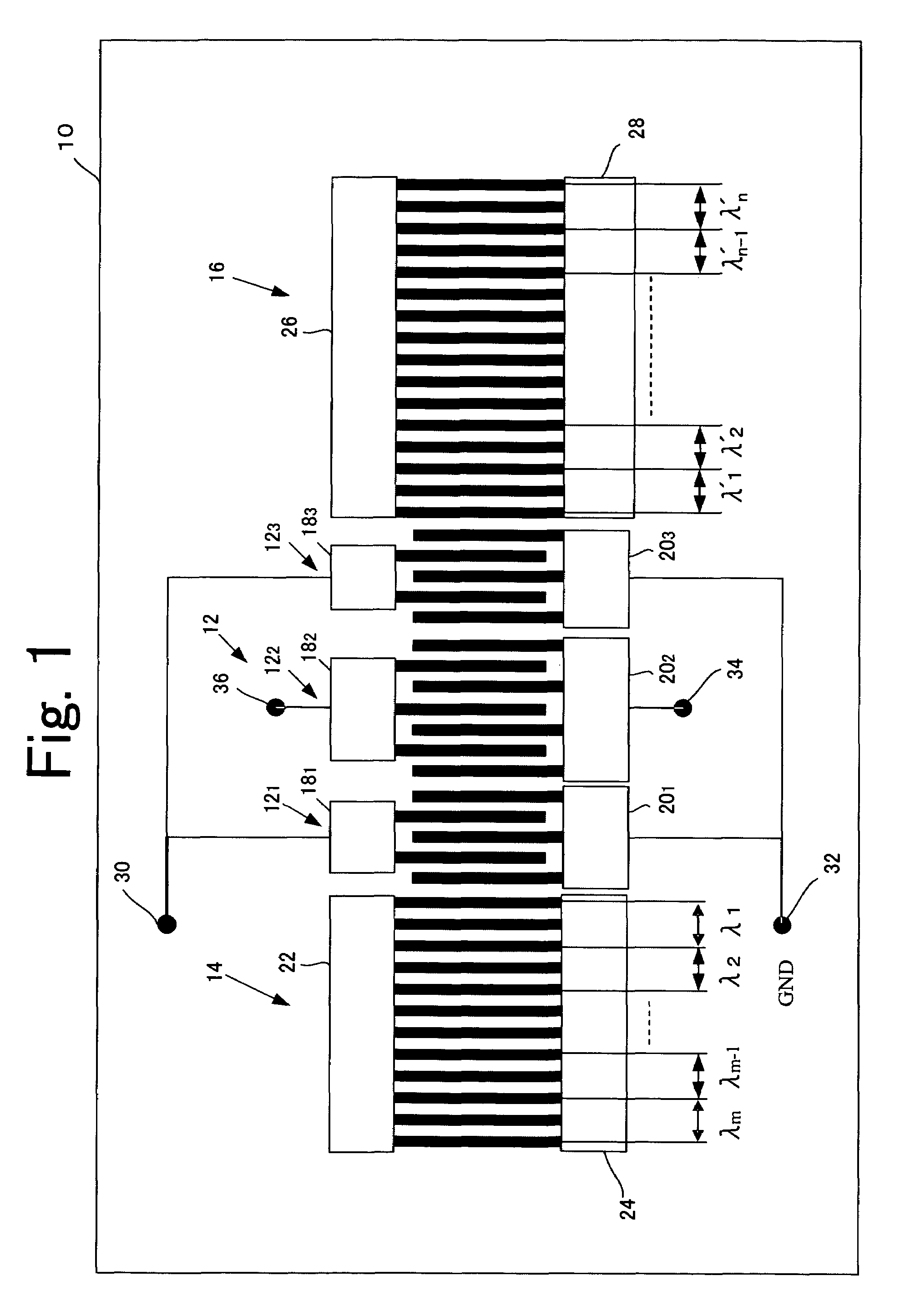
[0022]FIG. 1 illustrates a surface acoustic wave device in accordance with a first embodiment of the present invention. The surface acoustic wave device shown in FIG. 1 is a multi-mode (double-mode) surface acoustic wave device with the first-order (primary) mode and the third-order mode. This surface acoustic wave device includes a piezoelectric substrate 10, a drive electrode 12, and a pair of reflection electrodes 14 and 16. The drive electrode 12 and the reflection electrodes 14 and 16 are formed on the piezoelectric substrate 10. The piezoelectric substrate 10 is made of a piezoelectric material such as LiTaO3 or LiNbO3. The drive electrode 12 and the reflection electrodes 14 and 16 contain aluminum as a main component. The drive electrode 12 is interposed between the pair of reflection electrodes 14 and 16. The drive electrode 12 includes three electrodes 121, 122, and 123. Those three electrodes 121, 122, and 123 are so-called interdigital transducers. A bus...
second embodiment
(Second Embodiment)
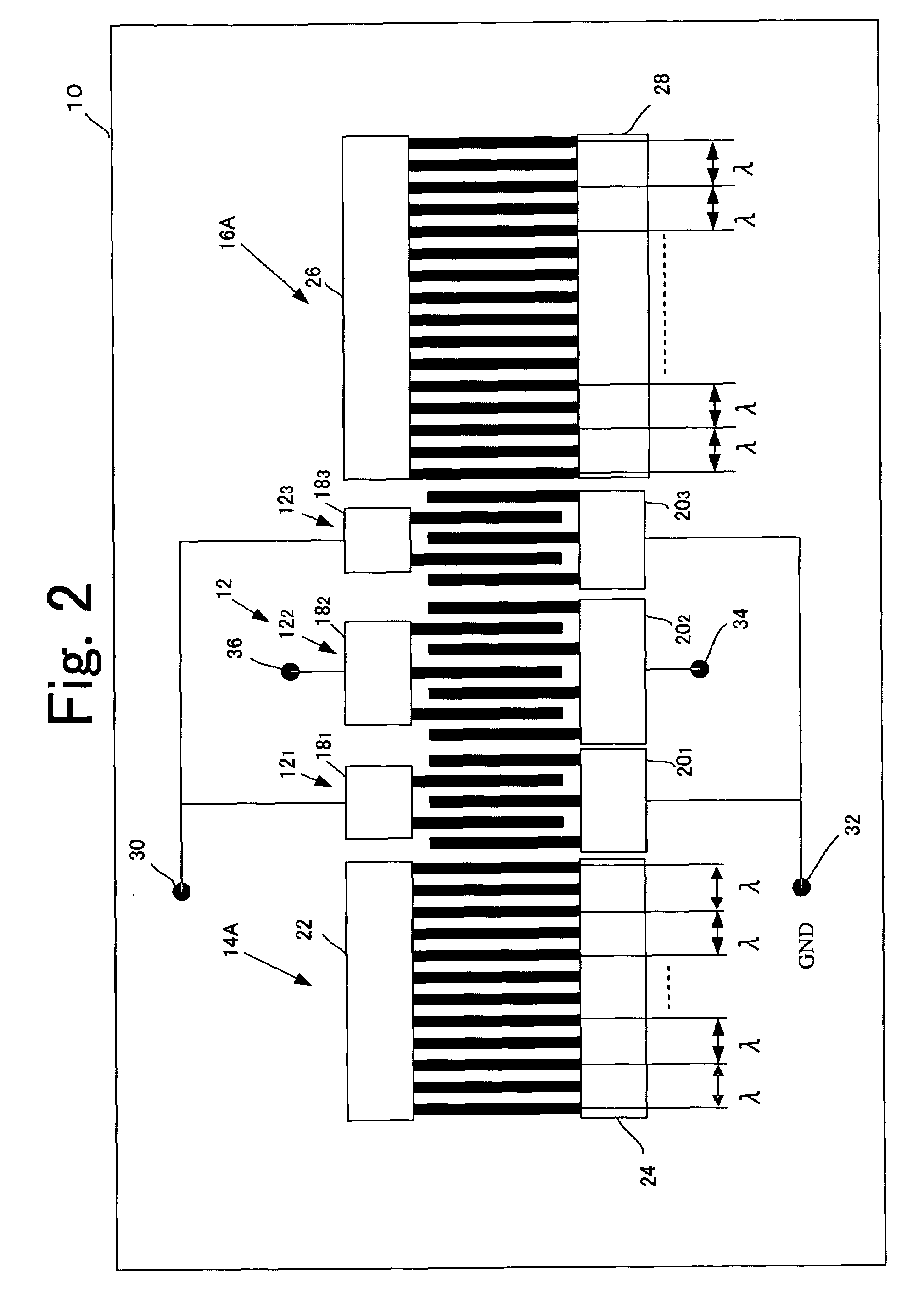
[0029]FIG. 5 illustrates a surface acoustic wave device in accordance with a second embodiment of the present invention. In FIG. 5, the same components as those described above are denoted by the same reference numerals used above.
[0030]The reflection electrode 14 shown in FIG. 5 is divided into blocks in accordance with the pitch characteristics. In the example shown in FIG. 5, the reflection electrode 14 is divided into three blocks BLK1, BLK2, and BLK3. For example, the blocks BLK1, BLK2, and BLK3 have uniform electrode pitches λ1, λ2, and λ3, respectively. The blocks BLK1, BLK2, and BLK3 may be the same or different in size (the number of electrode finger pairs contained therein). At least two of the blocks BLK1, BLK2, and BLK3 have different pitches from each other. More specifically, the relationship among the pitches is represented by one of the following expressions: λ1≠λ2, λ2≠λ3, λ1≠λ3, and λ1≠λ2≠λ3. Likewise, the reflection electrode 16 is divided into t...
example 1
[0041]Example 1 is a surface acoustic wave device of the second embodiment in which each of the reflection electrodes 14 and 16 is divided into three blocks. In this example, the number of electrode finger pairs in each of the blocks BLK1 and BLK′1 is 2, the number of electrode finger pairs in each of the blocks BLK2 and BLK′2 is 25, and the number of electrode finger pairs in each of the blocks BLK3 and BLK′3 is 24. The wavelengths λ1 and λ′1 of the blocks BLK1 and BLK′1 are both 4.525 μm (λ1=λ′1), the wavelengths λ3 and λ′3 of the blocks BLK3 and BLK′3 are both 4.525 μm (=λ1=λ′1), and the wavelengths λ2 and λ′2 (=λ2) of the blocks BLK2 and BLK′2 are 4.515 μm, 4.510 μm, and 4.505 μm. The piezoelectric substrate 10 is made of LiTaO3, and the drive electrode 12 and the reflection electrodes 14 and 16 contain aluminum as a main component.
[0042]FIG. 8 shows the frequency characteristics of Example 1. As can be seen from FIG. 8, the peak point (denoted by I in FIG. 8) of the pass band d...
PUM
 Abstract
Description
Claims
Application Information
 - R&D
- Intellectual Property
- Life Sciences
- Materials
- Tech Scout
- Unparalleled Data Quality
- Higher Quality Content
- 60% Fewer Hallucinations
Browse by: Latest US Patents, China's latest patents, Technical Efficacy Thesaurus, Application Domain, Technology Topic, Popular Technical Reports.
© 2025 PatSnap. All rights reserved.Legal|Privacy policy|Modern Slavery Act Transparency Statement|Sitemap|About US| Contact US: help@patsnap.com