
Detection method and detection device of special drugs

a detection method and detection device technology, applied in the direction of particle separator tube details, separation processes, instruments, etc., can solve the problems of low selectivity of mass analysis units, traffic congestion, and the possibility of issuing false reports

Active Publication Date: 2006-02-21
HITACHI HIGH-TECH CORP +1
View PDF16 Cites 13 Cited by
  • Summary
  • Abstract
  • Description
  • Claims
  • Application Information

AI Technical Summary

Benefits of technology

[0014]It is a first object of the present invention to provide a special drug detection method and its device that allow a sample pick-up to be easily performed from various types of check targets, and that make it possible to shorten the pick-up time and the checking time.
[0015]Also, it is a second object of the present invention to provide a special drug pick-up device that allows a sample pick-up to be easily performed from various types of check targets, and that makes it possible to shorten the pick-up time and the checking time.

Problems solved by technology

In this case, there exists a possibility of issuing a false report, i.e., the alarm is displayed despite the fact that no special drug is present.
This phenomenon, which is attributed to the low selectivity of a mass analysis unit for analyzing ions, is caused by its inability to distinguish between ions resulting from the stimulant and ions resulting from the cosmetics both of which have the same m / z value by chance.
This condition results in, e.g., an undesirable possibility of causing a traffic congestion of plural pieces of hand baggage flowing on board a hand-baggage transportation bench.
Nevertheless, this checking method still necessitates too much time because of its checking way, i.e., in the hand-baggage checking or the like, trouble is taken to open suitcases, briefcases, bags, parcels, and the like one by one, and the air around goods stored inside the hand baggage is absorbed.
However, there exist occasions where, depending on the type and packing style of the special drug, the special drug leaking from the baggage or the like is too small in amount, or the special drug is the type of special drug that is difficult to become the gas (i.e., vapors) at the room temperature.
On these occasions, merely absorbing the air on the surface of the check target by the absorption probe, in some cases, gives rise to a problem that the sample gas introduced into the mass spectrometer is insufficient in amount or concentration.
Also, if the check target on the check bench and the mass spectrometer are positioned with a considerable distance apart, it takes the sample gas a time to reach the ion-source via the pipe path such as the hose.
This results in a problem that the detection speed is lowered.
Nevertheless, the sample pick-up device disclosed in JP-A-5-332894 has the following problem: Namely, on the occasions where the special drug leaking from the baggage or the like is too small in amount, or the special drug is the type of special drug that is difficult to become the gas (i.e., vapors) at the room temperature, merely absorbing the air on the surface of the check target by the absorption fan, in some cases, gives rise to a problem that the picked-up sample is insufficient in amount or concentration.
Meanwhile, the sample pick-up device disclosed in JP-A-2-296128 has the following problem: Namely, if, when performing the checking continuously, a sample at a preceding checking remains on the collector without being fully vaporized, the reliability of the subsequent checking is lowered.
This results in a problem that the checking speed cannot be increased.
Also, if there exist the large number of check targets, the sample pick-up devices corresponding to the number of the check targets must be prepared, which is inconvenient.

Method used


Image

  • Detection method and detection device of special drugs
  • Detection method and detection device of special drugs
  • Detection method and detection device of special drugs

Examples


first embodiment

(First Embodiment)

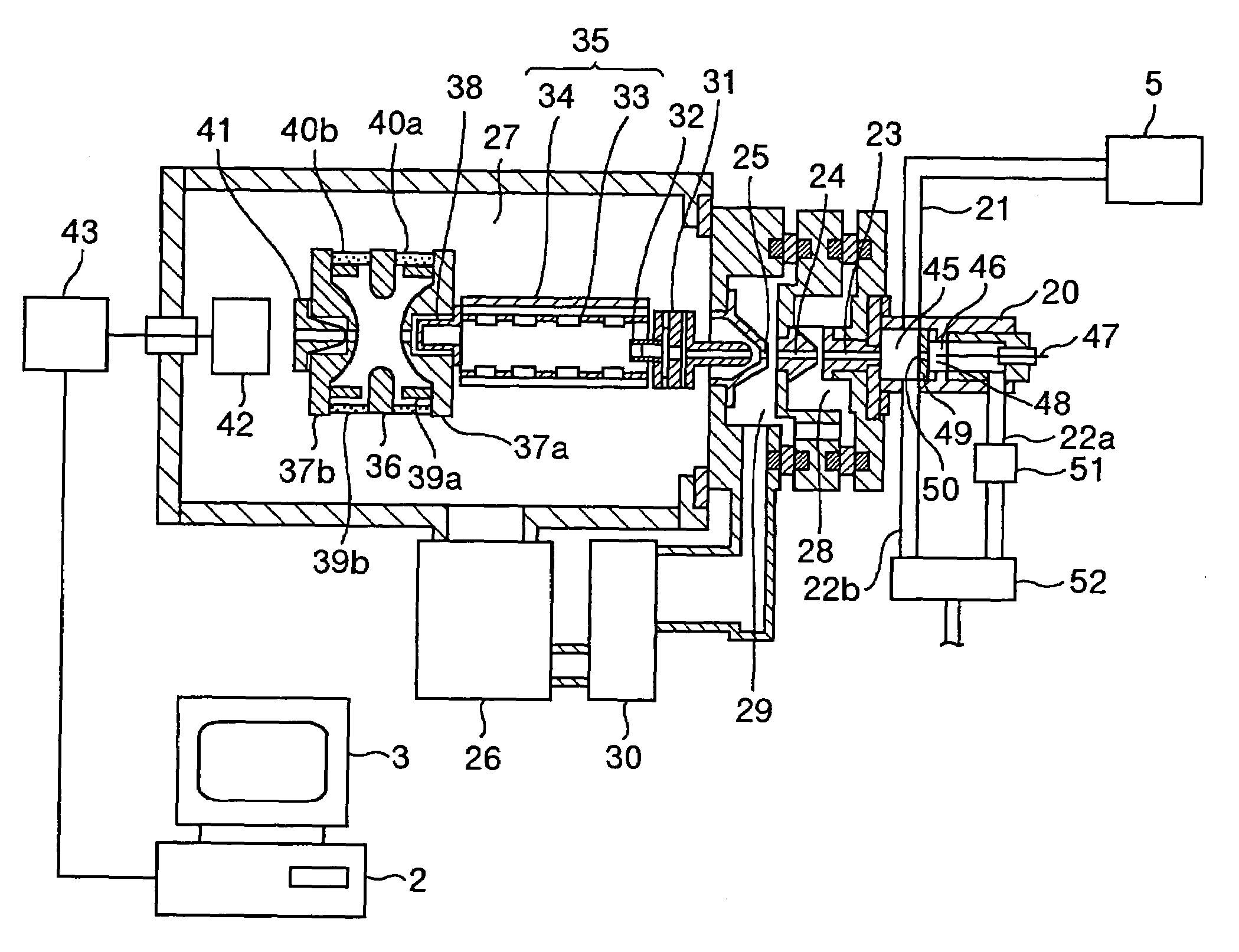
[0054]FIG. 1 is a configuration diagram for illustrating the main unit of a special drug detection device of an embodiment to which the present invention is applied. FIG. 2, FIG. 3, and FIG. 4 illustrate an outside-appearance front view of the present embodiment, a right side view thereof, and a left side view thereof, respectively. FIG. 5 to FIG. 7 illustrate a check-chip heater associated with characteristics of the present invention.

[0055]As illustrated in FIG. 2, the detection device of the present embodiment includes a main body 1 that stores therein a mass spectrometer 6, a data processing device 2, a display device 3, and the like. Casters 4 are provided at the bottom of the main body, which makes the detection device transportable. A heater 5 is provided on the upper portion of a housing of the main body 1. Also, in the drawing, the reference numerals denote the following configuration components: 7 a vacuum pump (: 26 in FIG. 1), 8 a roughing pump (: 30 in...

second embodiment

(Second Embodiment)

[0081]The embodiment illustrated in FIG. 5 is as follows: The opposed heating plate 102 is configured to be in the lift-up / lift-down-capable manner. Next, the spacing between the opposed heating plate 102 and the absorption heating plate 101 is enlarged, then inserting the check chip 8 into the spacing therebetween. After that, the spacing is narrowed down to a predetermined spacing, then performing the measurement and the heating. In substitution for this, the following embodiment is preferable: The spacing between the opposed heating plate 102 and the absorption heating plate 101 is fixed beforehand, then inserting the check chip 8 into the clearance therebetween.

[0082]Here, referring to FIGS. 8A and 8B, the explanation will be given below regarding influences exerted on the measurement by the spacing between the opposed heating plate 102 and the absorption heating plate 101. At first, for the explanation, the following assumption is made: Two types of substance...

third embodiment

(Third Embodiment)

[0087]FIG. 11 illustrates another embodiment of the main-body unit of the heater 5 including the absorption heating plate 101 and the opposed heating plate 102 according to the embodiment in FIG. 5. The present embodiment is as follows: The check chip 8 is fixed by being sandwiched between the absorption heating plate 101 and the opposed heating plate 102 through the contacts therewith, then vaporizing the sample 7. Namely, as illustrated in FIG. 11, protrusions 112 in a constant height are provided along the circumferential portion of the heating surface of the absorption heating plate 101 according to the present embodiment in a direction heading from the center to the circumferential direction. Between the respective protrusions 112, a groove-shaped absorption opening 113 is formed which is capable of absorbing the surrounding atmosphere-gas. The configuration of each absorption opening 113 is no specific problem, as long as each opening 113 is routed to the ins...


PUM

PropertyMeasurementUnit
diameteraaaaaaaaaa
pressureaaaaaaaaaa
pressureaaaaaaaaaa

Abstract

Firstly, the following check chip is set up into a heater: A check chip onto which a sample has been picked up by wiping out the surface of a check target, or a check chip formed by absorbing and collecting the sample into a filter. Here, the filter has been set up in a vibration-type or heating-type portable-type absorption probe in an attachment / detachment-capable manner. Secondly, a sample gas generated from the heated check chip is analyzed using a tandem-type mass spectrometer. This makes it possible to simplify the sample pick-up from various types of check targets, and to shorten the pick-up time and the checking time.

Description

BACKGROUND OF THE INVENTION[0001]1. Field of the Invention[0002]The present invention relates to detection technologies for gunpowder-kind materials such as explosive substances, dangerous objects such as flammable substances, poisonous gases, and legally prohibited medications such as drugs (all of which, hereinafter, will be generically referred to as “special drugs” for convenience). More particularly, it relates to a detection method and its device that, by using a mass spectrometer, detect whether or not a special drug is present inside, e.g., baggage such as a piece of hand baggage, freight, and a suspicious object.[0003]2. Description of the Related Art[0004]Generally speaking, in such locations as an airport and an event grounds where a large number of people come and gather, a detection device has become necessary which is designed for detecting special drugs such as an explosive substance. This detection device is requested for implementing the safety of passengers and eve...

Claims


Application Information

Patent Timeline
Patent Type & Authority Patents(United States)
IPC IPC(8): H01J49/42G01N27/62G01N1/00G01N1/02G01N1/22G01N1/24G01N33/15G01N33/22H01J49/04
CPCG01N1/2214H01J49/004G01N1/24G01N2001/024G01N2001/028G01N33/22
Inventor ISHIKAWA, MASAKIMATSUMOTO, MASAKINISHIKAWA, YOSHIHIROTAKADA, YASUAKINAGANO, HISASHISAKAMOTO, MASAMI
Owner HITACHI HIGH-TECH CORP
Learn More