
Method and system for heating solid tissue

Inactive Publication Date: 2006-02-21
BOSTON SCI SCIMED INC
View PDF33 Cites 273 Cited by
  • Summary
  • Abstract
  • Description
  • Claims
  • Application Information

AI Technical Summary

Benefits of technology

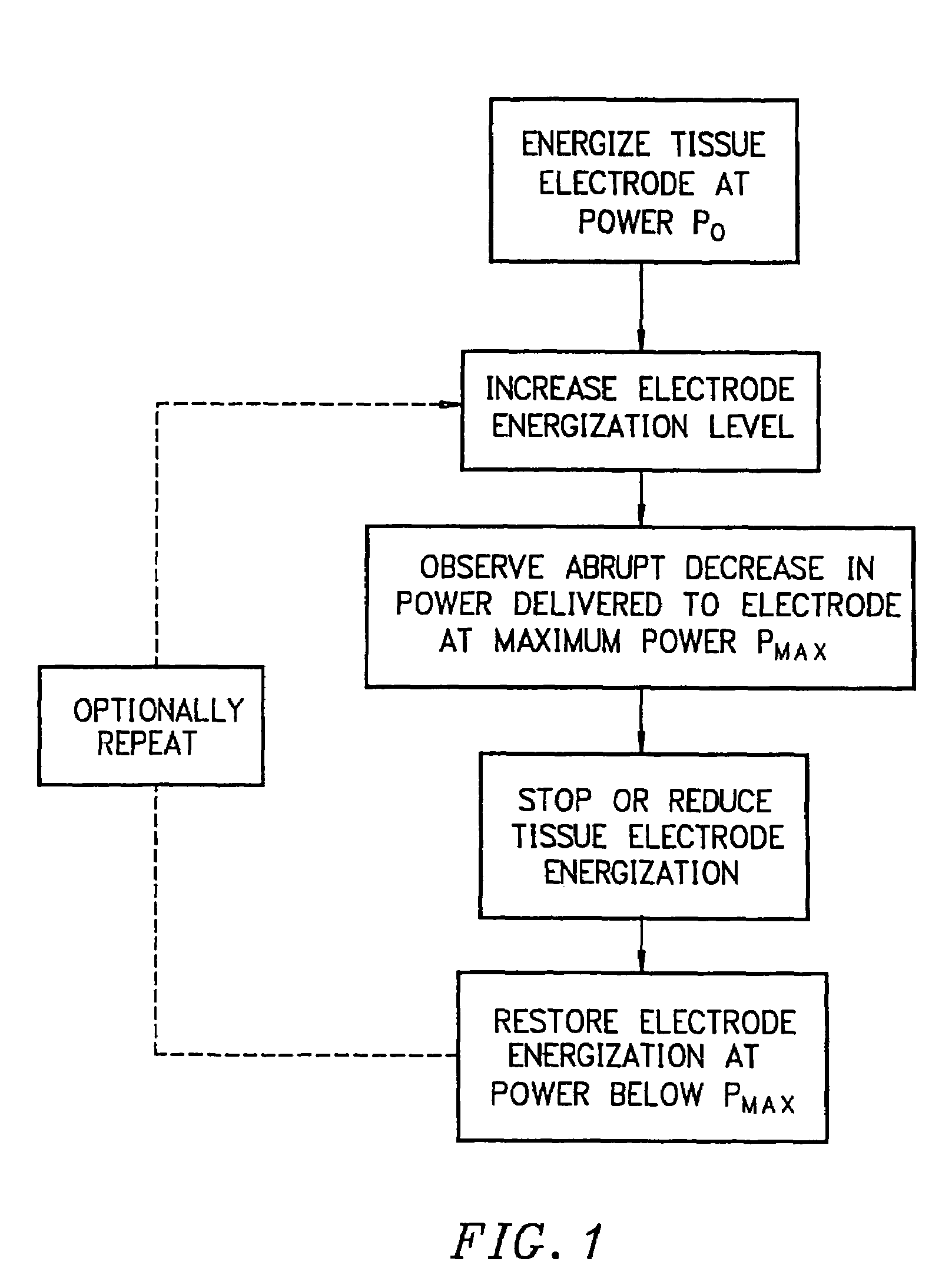
[0016]It is presently believed that the abrupt increase in electrode-tissue interface impedance results from the formation of a thin gaseous layer over the electrode surface, apparently resulting from vaporization of water within the tissue as the temperature approaches the local boiling point. Surprisingly, the thin gaseous layer appears to spread from an initial nucleation site to cover most or all of an electrode surface in a very short time period, typically less than 30 seconds, resulting in an increase in electrode-tissue interface impedance which is very large when compared to the total system impedance prior to formation of the thin gaseous layer. In the exemplary systems described herein after, typical system impedance prior to formation of the thin gaseous layer will be in the range from 40 Ù to 70 Ù, which impedance will rise to from 300 Ù to 400 Ù after formation of the thin gaseous layer. While this is presently believed to be the mechanism responsible for the above-described observations, the present invention does not depend on the accuracy of this model. The methods, systems, and apparatus of the present invention have been found to be useful and effective regardless of the actual mechanism which is responsible for the change in impedance.

Problems solved by technology

It has been found that the delivery of radio frequency power to electrode(s) disposed in tissue can, if the power is delivered for a sufficient time and / or at a sufficient power delivery level or flux, result in an abrupt increase in the electrical impedance between the electrode(s) and tissue.

Method used


Image

  • Method and system for heating solid tissue
  • Method and system for heating solid tissue
  • Method and system for heating solid tissue

Examples


Embodiment Construction

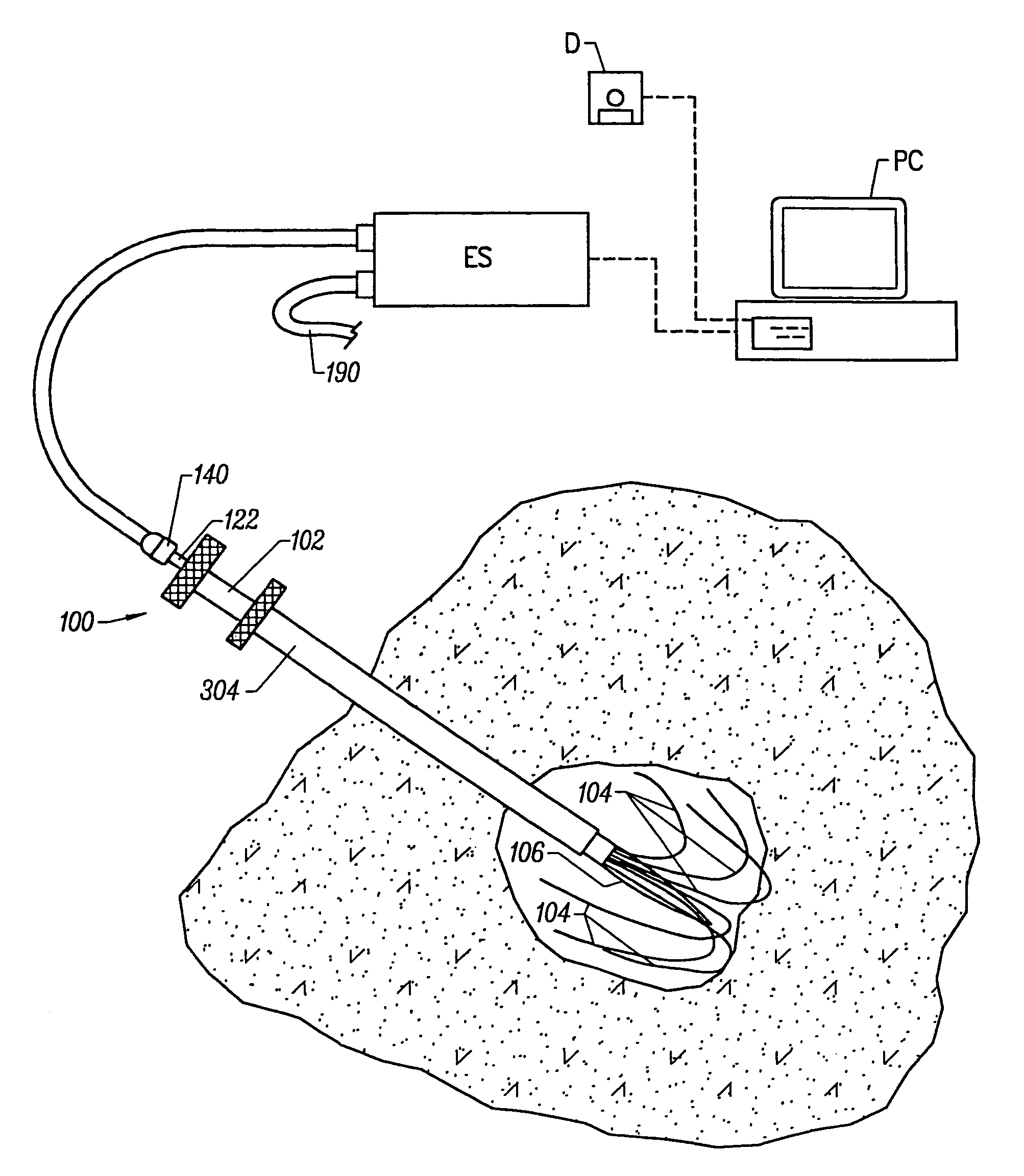
[0031]Methods, systems, and apparatus according to the present invention will rely on placement and use of one or more electrode element(s) positioned at or within a treatment region within solid tissue of a patient. The treatment region may be located anywhere in the body where hyperthermic exposure may be beneficial. Most commonly, the treatment region will comprise a solid tumor within an organ of the body, such as the liver, kidney, lung, bowel, stomach, pancreas, breast, prostate, uterus, muscle, and the like. The volume to be treated will depend on the size of the tumor or other lesion, typically having a total volume from 1 cm3 to 150 cm3, usually from 1 cm3 to 50 cm3, and often from 2 cm2 to 35 cm2. The peripheral dimensions of the treatment region may be regular, e.g. spherical or ellipsoidal, but will more usually be irregular. The treatment region may be identified using conventional imaging techniques capable of elucidating a target tissue, e.g. tumor tissue, such as ult...


PUM


Abstract

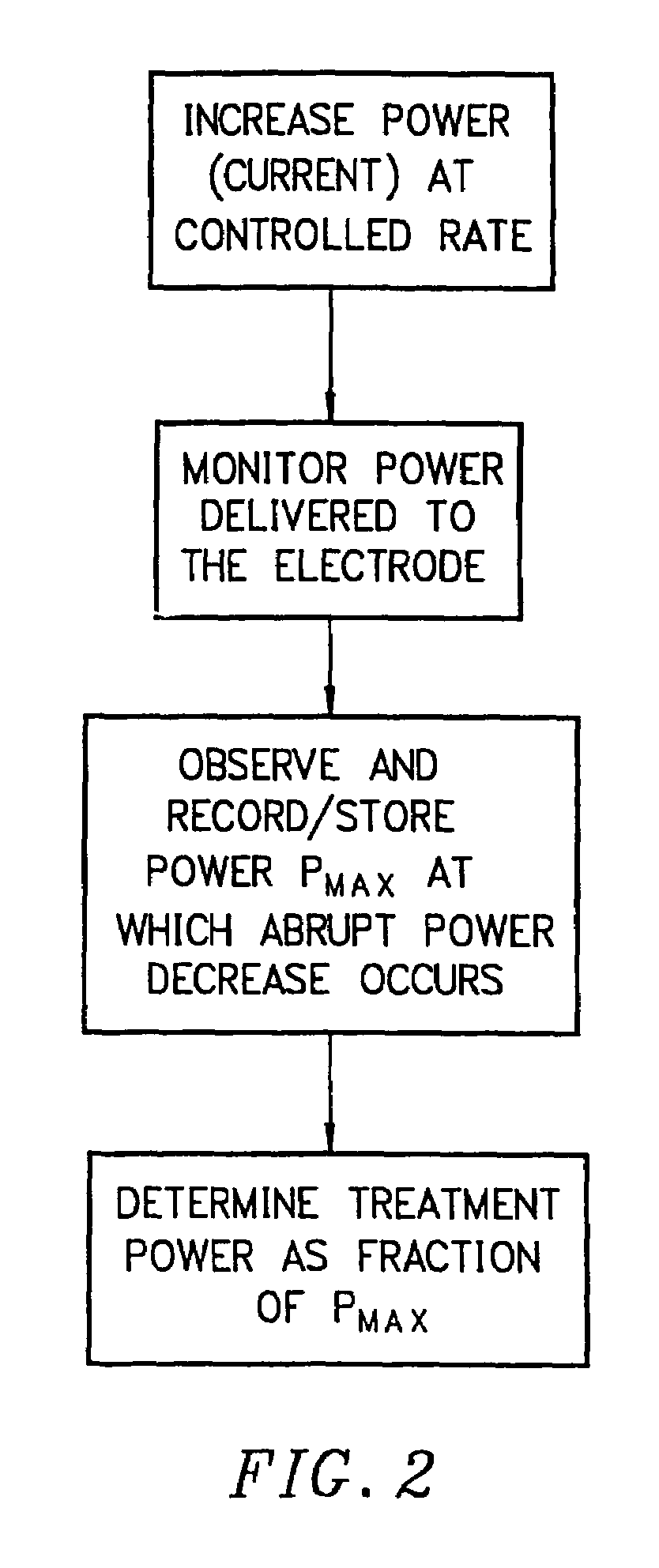
Method for heating tissue by delivering radio frequency energy through tissue electrodes having controlling energy delivery so that an abrupt increase in impedance between the electrodes and the tissue is observed, typically in the form of an abrupt decrease in power delivered to the electrodes. The power at which the impedance increases and / or the time required to induce such an increase in impedance, are relied on to determine acceptable ranges to achieve a maximum sustainable delivery of radio frequency energy to the tissue consistent with complete, rapid, and uniform heating of the tissue.

Description

CROSS-REFERENCES TO RELATED APPLICATIONS[0001]This application is a continuation of and claims the benefit of priority from application Ser. No. 09 / 992,734, filed on Nov. 13, 2001, now U.S. Pat. No. 6,685,700, which is a continuation of and claims the benefit of priority from application Ser. No. 09 / 344,822, filed on Jun. 25, 1999, now U.S. Pat. No. 6,358,246, which is a continuation of and claims the benefit of priority from application Ser. No. 08 / 936,294, filed on Sep. 25, 1997, now U.S. Pat. No. 5,954,717, the full disclosures of which are incorporated herein by reference.BACKGROUND OF THE INVENTION[0002]1. Field of the Invention[0003]The present invention relates generally to the use of radio frequency energy for heating and necrosing solid tissue. More particularly, the present invention relates to a control method and system for delivering radio frequency current to the tissue through an electrode or electrode array disposed within the tissue.[0004]The delivery of radio frequ...

Claims


Application Information

Patent Timeline
IPC IPC(8): A61B18/04A61B18/14
CPCA61B18/1482A61B18/1477A61B2018/00702A61B2018/1475A61B2018/1425A61B2018/143A61B2018/00875
Inventor BEHL, ROBERT S.KERMIT, EBEN L.LYONS, PETER F.NICHOLS, COLIN J.
Owner BOSTON SCI SCIMED INC
Learn More