
Non-pyrolytically actuated reduced-shock separation fastener

a non-pyrolytic actuator and fastener technology, applied in the direction of thread fasteners, cosmonautic vehicles, transportation and packaging, etc., can solve the problems of inability to accommodate for such forces, the inability to release preload energy, and the inability to produce strong mechanical shocks. , to achieve the effect of relieved axial tensile preload and reduced axial thickness

Inactive Publication Date: 2006-02-21
HI SHEAR TECH
View PDF5 Cites 23 Cited by
  • Summary
  • Abstract
  • Description
  • Claims
  • Application Information

AI Technical Summary

Benefits of technology

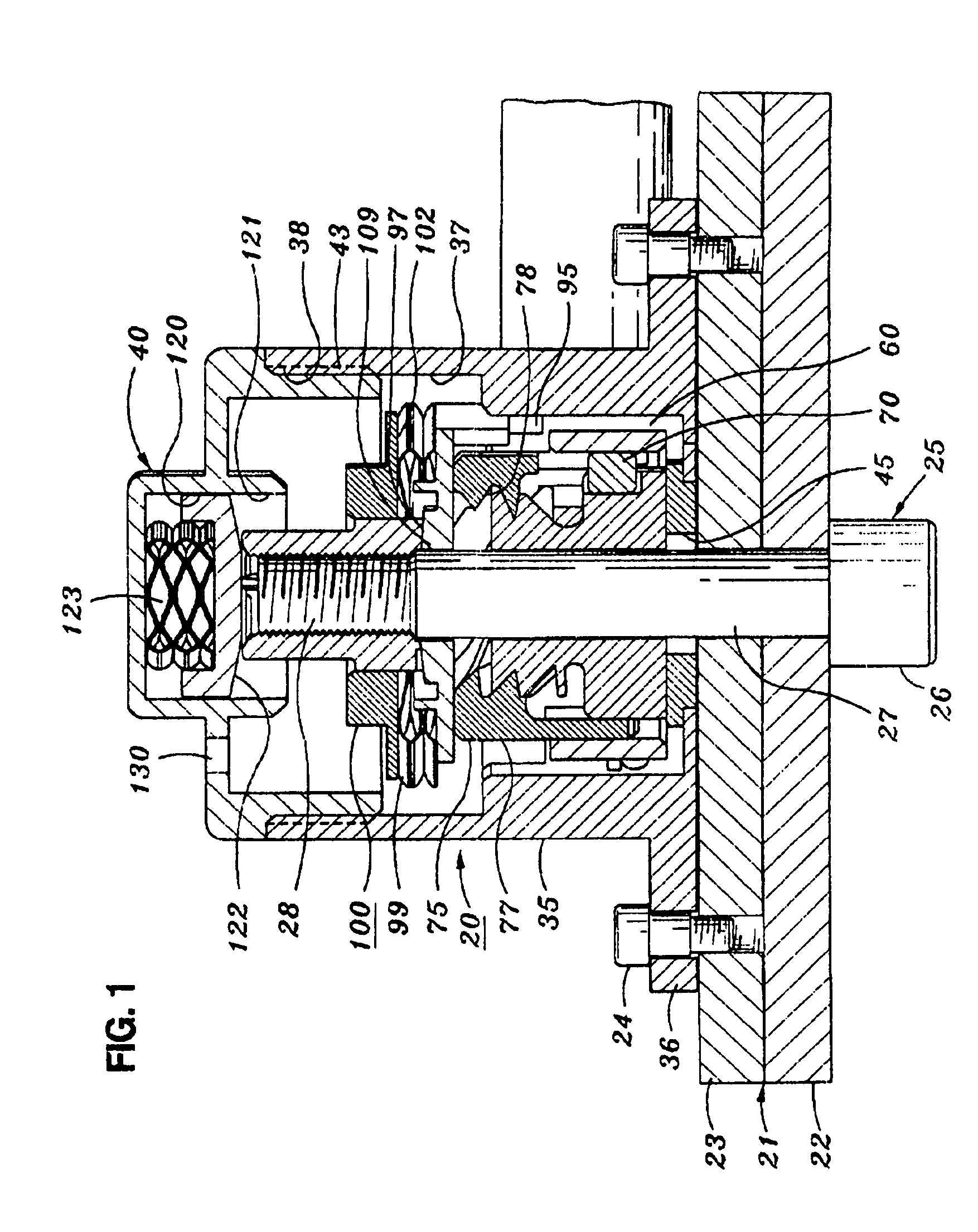
[0012]The ramp angle is steeper than a locking angle, so that an axial compressive force will exert a rotational force on the rotor, the stator being keyed to the housing to prevent its rotation. Rotation of the rotor (when it is free to rotate) will result in a reduction of the axial thickness of the relief element, and will thereby relieve the axial tensile preload.
[0015]Thus, with this invention, peak release loads are greatly reduced, and pyrolytic loads are eliminated entirely. Instead, a gradual force exerted laterally and rotationally balanced is used instead for unlocking the rotor and stator from one another, and energy stored in springs separate the threaded segments from the bolt to release the bolt.

Problems solved by technology

It customarily results in an abrupt release of the preload energy and is therefore objectionable, although necessary.
In addition to the mechanical shock caused by abrupt release of the axial preload in the installed fastener, a pyrolytic actuator inherently produces a strong mechanical shock because of its abrupt generation of force.
Then the need to accommodate for such forces is an accepted disadvantage.
Such accommodation can have its price in weight and structure.

Method used


Image

  • Non-pyrolytically actuated reduced-shock separation fastener
  • Non-pyrolytically actuated reduced-shock separation fastener
  • Non-pyrolytically actuated reduced-shock separation fastener

Examples


Embodiment Construction

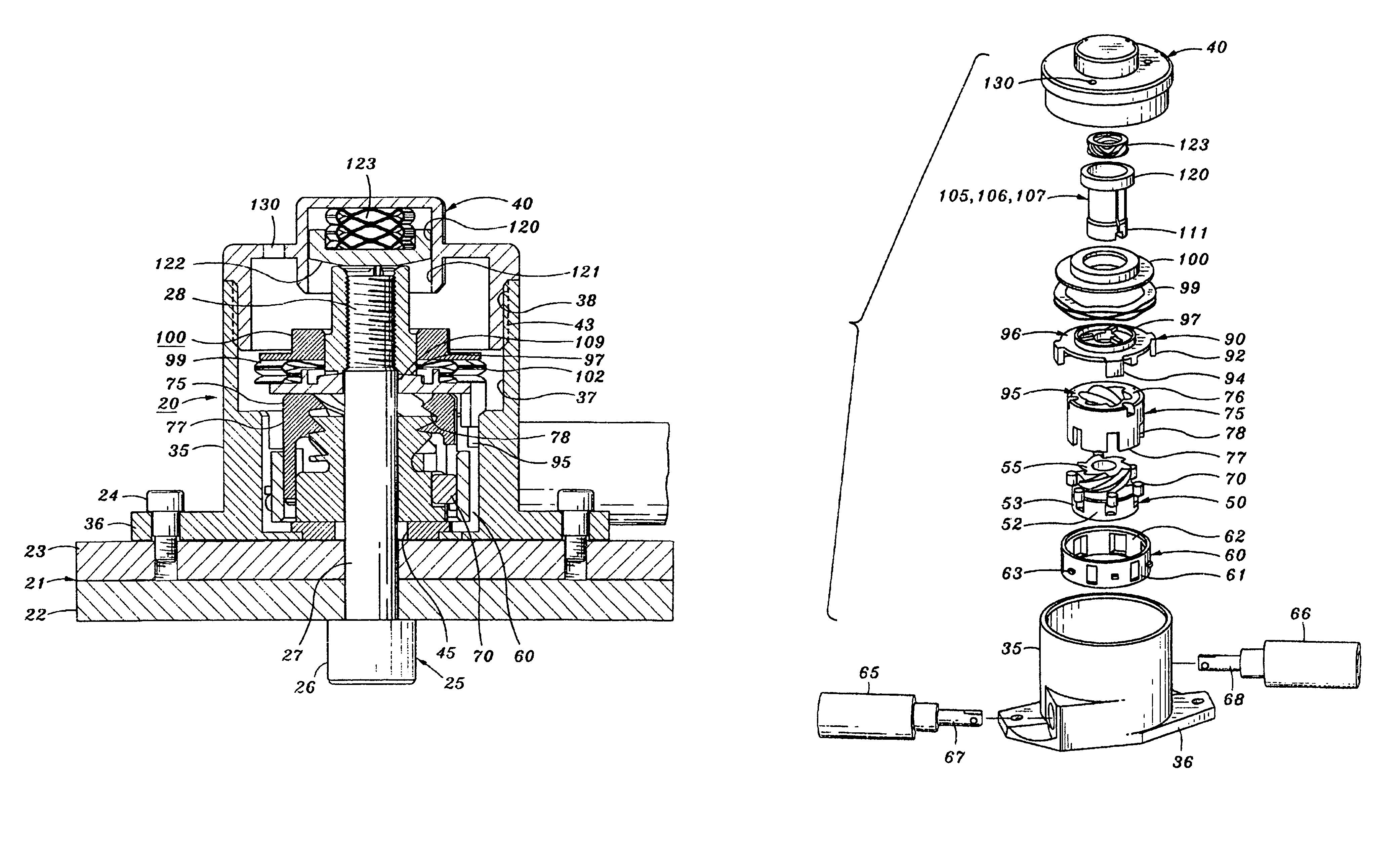
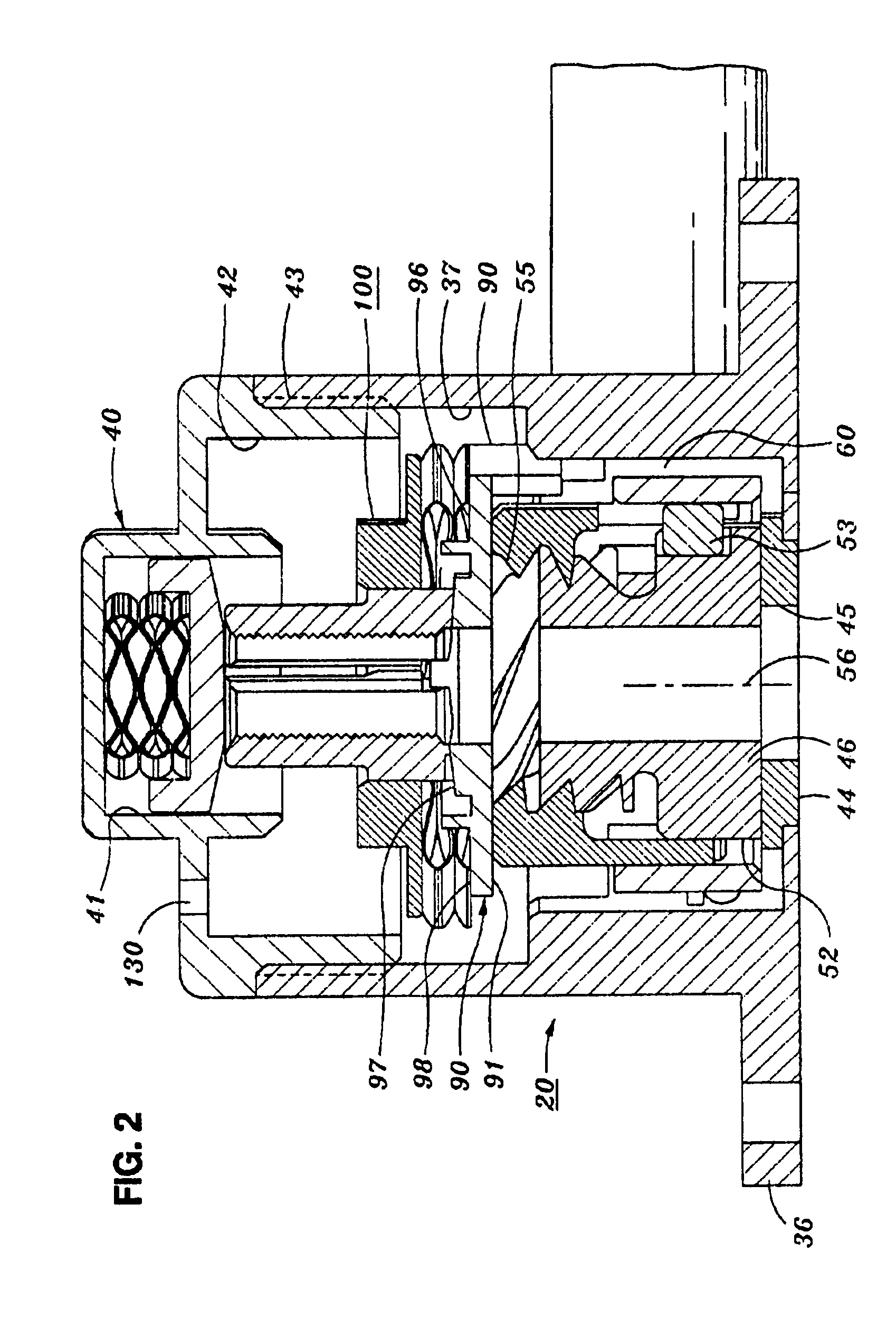
[0023]The utility of a fastener 20 according to this invention is shown in FIG. 1. It forms part of a structural assembly 21. As an example, one object 22, exemplified as a plate to which any desired element can be mounted is held to another object 23, again shown as a plate. These objects are to be held together by fastener 20 until the moment of separation.

[0024]The fastener is fixed to plate 23 by bolts 24 or by other fastener devices. A bolt 25 with a head 26, a shank 27 and a thread 28 on the shank is threaded into fastener 20. Tightening the bolt into a nut to be described holds the objects together. When they are joined, the torque on the bolt exerts through the threads an axial tensile preload force that tightly holds the objects together. The release of the energy stored in the bolt will, unless regulated, exert a strong impact force on the entire structure.

[0025]Fastener 20 includes a body 35 with a mounting flange 36 and a rising tubular housing 37. The housing has an int...


PUM


Abstract

A separable fastener for holding two objects together with the use of a bolt threaded into the fastener. The necessary inherent axial tension in the bolt / fastener system is accommodated by a relief element which relieves at least some of the stored tension before the nut separates, thereby reducing the physical shock on the assembly. The energy needed to separate the nut and bolt is entirely contained within the system so that pyrotechnic devices are unnecessary for the purpose.

Description

FIELD OF THE INVENTION[0001]A separable threaded fastener for releasing one object from another in a structure, utilizing an actuator which is other than pyrolytic so as to reduce mechanical shock otherwise caused by abruptly expansive gases, and by the abrupt release of axial tensile force in the assembled structure. In addition, the fastener can be reset for a subsequent use without requiring new components.BACKGROUND OF THE INVENTION[0002]Especially, although far from exclusively, in the aerospace field objects are held together as part of a structure by means of separable fasteners. Their purpose is to separate the objects from one another on command, meanwhile holding them reliably in the presence of high G loads and strong vibration forces. Such fasteners must themselves be very strong and reliable, and must be able to withstand the same forces as the objects they hold.[0003]Classically such fasteners comprise an internally threaded nut held by one of the objects and an extern...

Claims


Application Information

Patent Timeline
Patent Type & Authority Patents(United States)
IPC IPC(8): F16B37/08B64G1/64
CPCF16B37/0864B64G1/645
Inventor TUSZYNSKI, ANDREW
Owner HI SHEAR TECH
Learn More