
Vehicle cowl structure with vent pipe

a technology of vent pipe and cowl structure, which is applied in the direction of vehicle maintenance, vehicle cleaning, roof, etc., can solve the problems of affecting the draining of water, unable to introduce sufficient outside air into the cowl structure for the vehicle ventilation system through the air inlets,

Inactive Publication Date: 2006-02-21
NISSAN MOTOR CO LTD
View PDF17 Cites 20 Cited by
  • Summary
  • Abstract
  • Description
  • Claims
  • Application Information

AI Technical Summary

Benefits of technology

[0008]One object of the present invention is to provide a cowl structure that overcomes this problem of draining water from the cowl structure when the outside air being sucked into the cowl structure through the water drainage openings of the cowl structure.

Problems solved by technology

It has been discovered that in some conventional cowl structures, when the air inlets of the cowl louver is covered by, for example, snow in the winter time, sufficient outside air cannot be introduced into the cowl structure for the vehicle ventilation system through the air inlets.
However, the outside air being sucked into the cowl structure through the water drainage openings interferes with the draining of the water from the cowl structure to the outside.

Method used


Image

  • Vehicle cowl structure with vent pipe
  • Vehicle cowl structure with vent pipe
  • Vehicle cowl structure with vent pipe

Examples


Embodiment Construction

[0024]Selected embodiments of the present invention will now be explained with reference to the drawings. It will be apparent to those skilled in the art from this disclosure that the following descriptions of the embodiments of the present invention are provided for illustration only and not for the purpose of limiting the invention as defined by the appended claims and their equivalents.

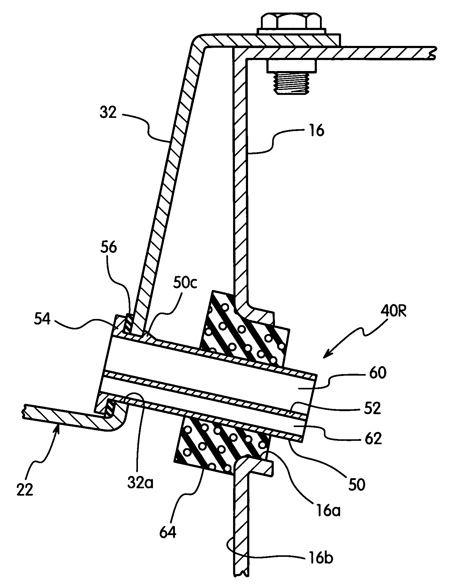
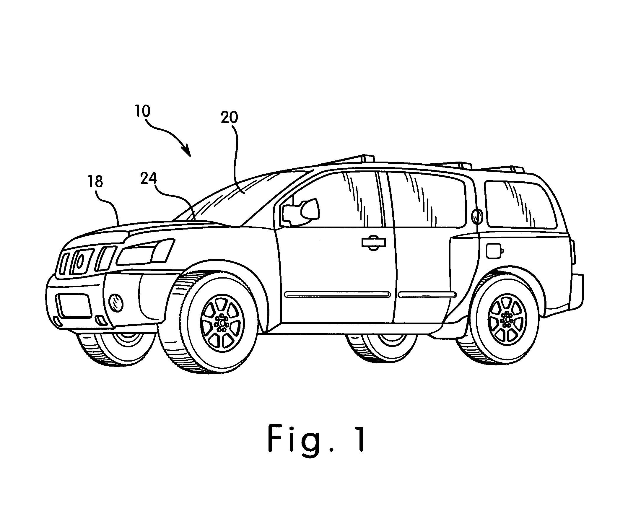
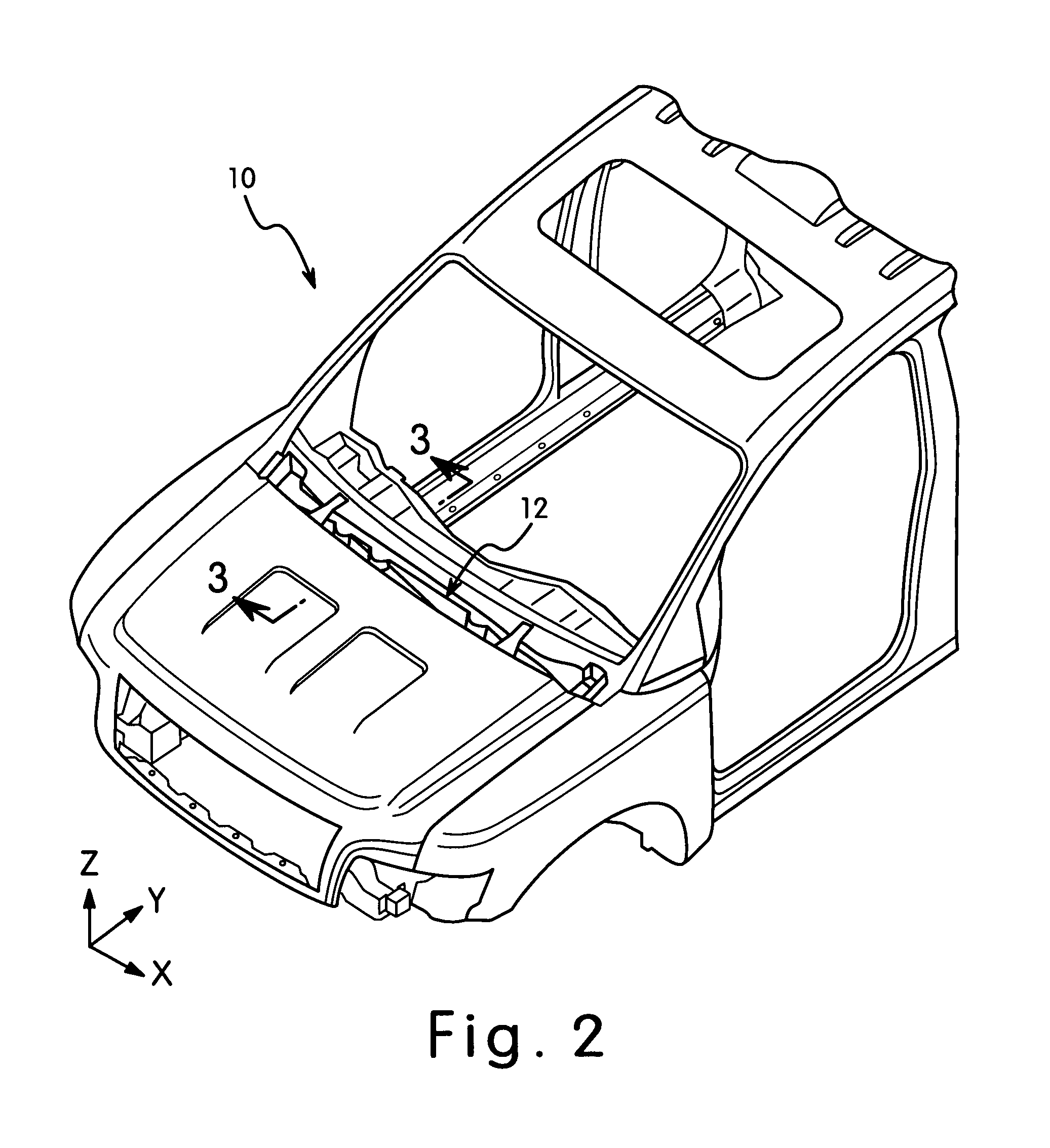
[0025]Referring initially to FIGS. 1–5, a portion of a vehicle body 10 is illustrated that is equipped a vehicle cowl structure 12 in accordance with a preferred embodiment of the present invention. The precise construction of the vehicle body 10 is not important to the present invention. Thus, simplified illustrations of the vehicle body 10 will be used to describe the present invention. Also since the majority of the structure of the vehicle 10 is conventional and / or not important to the present invention, only those parts or portions of the vehicle body 10 that relate to the present invention wi...


PUM


Abstract

A vehicle cowl structure basically comprises a cowl panel and a vent pipe disposed in the cowl panel at a low drainage point on a lateral wall portion of the cowl panel. The vent pipe includes an opening that is split by a divider into an upper air passageway and a lower water drain passageway. The vent pipe also includes a mounting flange that contacts with an interior surface of the lateral wall portion and retaining projections to create a snap-fit between the vent pipe and the drainage aperture of the cowl panel. The vent pipe is also inserted into a hole formed in a vehicle body section such that a retaining member installed over the vent pipe contacts the vehicle body section around the hole and seals a space between the vent pipe and the hole of the vehicle body member.

Description

BACKGROUND OF THE INVENTION[0001]1. Field of the Invention[0002]The present invention generally relates to a vehicle cowl structure with vent pipe. More specifically, the present invention relates to a vehicle cowl structure having a cowl panel with a vent pipe that includes an upper passageway for introducing air into the cowl panel and a lower passageway for draining water from the cowl panel.[0003]2. Background Information[0004]Generally, a vehicle includes a cowl structure that is disposed in an area between a front windshield and a fire wall of an engine room to divide the engine room and an interior part of the vehicle. The cowl usually comprises a cowl panel and a cowl louver provided on the cowl panel to cover an upward opening of the cowl panel. The cowl louver is provided with air inlets so that an outside air is drawn to the cowl. The air drawn to the cowl is used for the air conditioning and / or directly sent to the vehicle interior through a duct coupling the cowl and th...

Claims


Application Information

Patent Timeline
Patent Type & Authority Patents(United States)
IPC IPC(8): B62D25/08
CPCB60H1/28B62D25/081
Inventor BORKOWSKI, SLAVYAMAMOTO, YOUICHI
Owner NISSAN MOTOR CO LTD
Learn More