
Drillpipe spinner

a technology of drill pipe and spinner, which is applied in the direction of drilling casings, wrenches, drilling pipes, etc., can solve the problems of inefficient time-consuming replacement of the entire spinner with another spinner, and inability to replace the whole spinner, so as to minimize the downtime of the rig, easy removal, and easy replacemen

Active Publication Date: 2006-02-21
NAT OILWELL DHT
View PDF20 Cites 56 Cited by
  • Summary
  • Abstract
  • Description
  • Claims
  • Application Information

AI Technical Summary

Benefits of technology

"The invention is an improved drill pipe spinner that allows for easy repair and replacement of rollers. The spinner has clamps that can be opened and closed to handle pipes, and the rollers are attached to the clamps with a removable bracket that can be easily replaced. This design reduces downtime on the rig and minimizes the need for inventory of drill pipe spinners."

Problems solved by technology

This typically means that the entire spinner is replaced due to the complexity of the spinning unit and the time necessary to repair, service or replace the same.
However, the replacement of the entire spinner with another spinner apparatus is still time consuming as well as inefficient in the number of spinners that must be maintained in inventory at any given point in time, either at the rig site, back at the service facility, or in transport there between.

Method used


Image

  • Drillpipe spinner
  • Drillpipe spinner
  • Drillpipe spinner

Examples


Embodiment Construction

[0019]The following examples are included to demonstrate preferred embodiments of the invention. It should be appreciated by those of skill in the art that the techniques disclosed in the examples which follow represent techniques discovered by the inventor to function well in the practice of the invention, and thus can be considered to constitute preferred modes for its practice. However, those of skill in the art should, in light of the present disclosure, appreciate that many changes can be made in the specific embodiments which are disclosed and still obtain a like or similar result without departing from the spirit and scope of the invention.

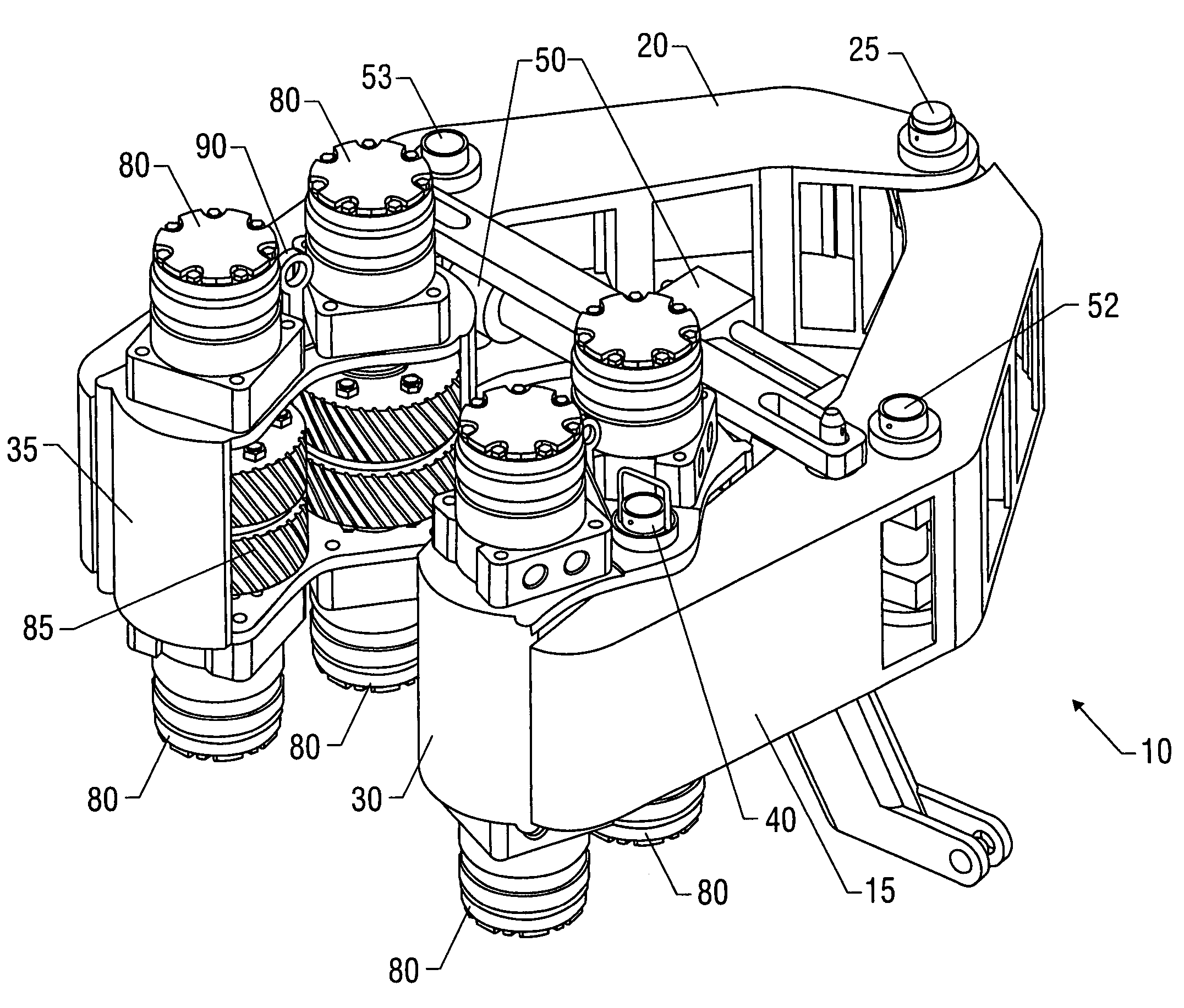
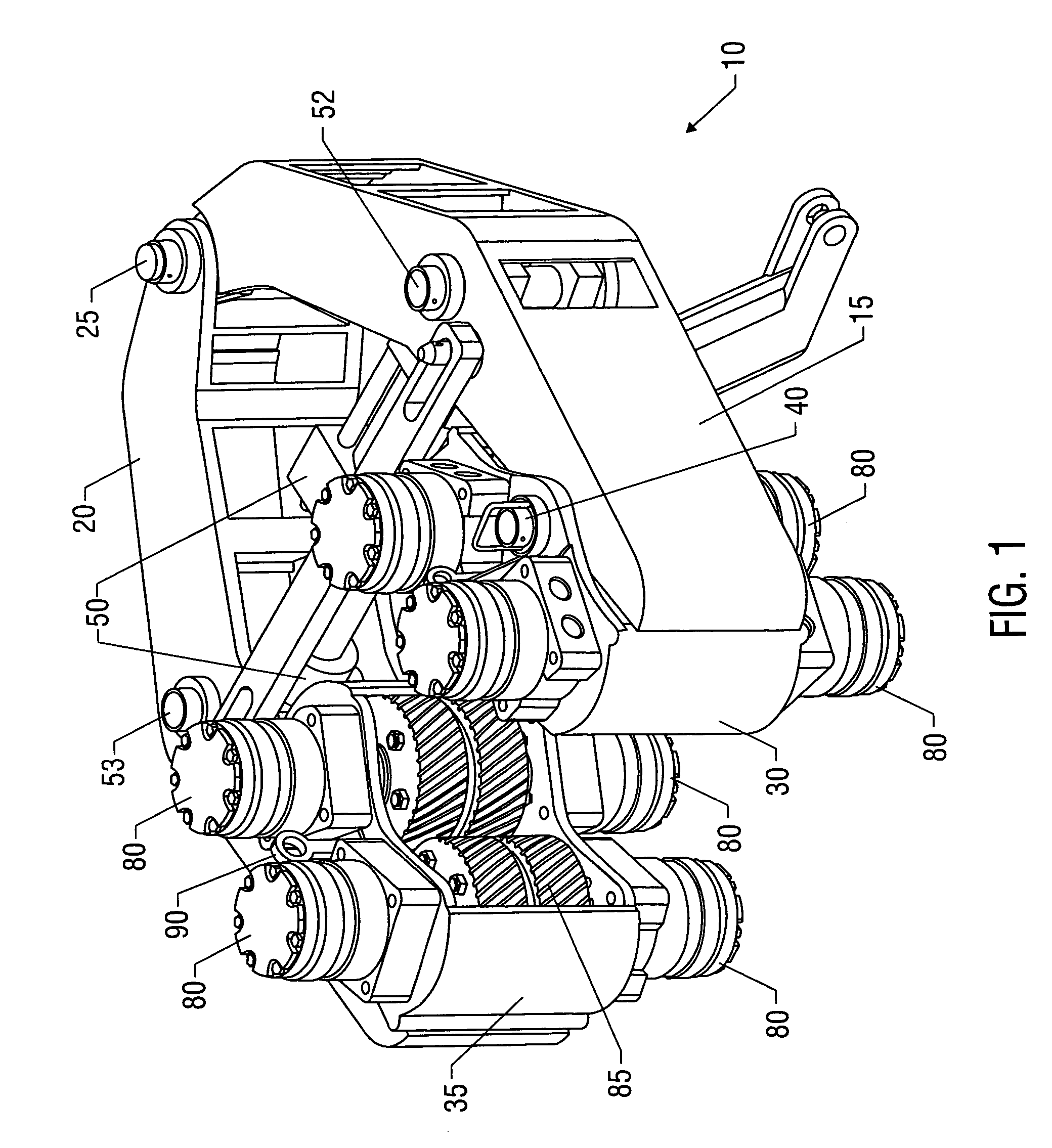
[0020]FIG. 1 illustrates a preferred embodiment of the improved drill pipe spinner 10 of the present invention. The drill pipe spinner includes a pair of clamping arms 15 and 20, which are pivotably connected together at one end by arm pin 25. Arms 15 and 20 are movable between an open position and a closed position, wherein the closed posi...


PUM


Abstract

The invention relates to an improved drill pipe spinner. The improved spinner may be used as a stand-alone piece of pipe handling equipment or may be used in an Iron Roughneck. The spinner comprises a pair of clamping arms that are movable between an open position and a closed position, wherein in the closed position, the arms will clamp about a pipe to be made up or broken out and in the open position, the spinner may be moved away from or towards the pipe. The arms are preferably moved between the open and closed positions by a hydraulically actuated clamping cylinder. Attached to the distal ends of each arm is a roller bracket. The roller brackets are preferably attached to the clamping arms by a roller bracket pin. Each roller bracket includes a pair of drive roller assemblies, which together form the spinning unit. Each drive roller assembly preferably comprises a pair of drive rollers, with each roller rotated by a pair of hydraulic motors. If the rollers of the spinner have to be repaired, serviced or replaced, the arm brackets are easily removed by simply pulling the roller bracket pin and removing the roller bracket. A new roller bracket may then be picked up, aligned with and pinned to the arm by reinserting the roller bracket pin. The spinning unit can easily be removed and replaced on the rig floor by changing out the roller bracket.

Description

FIELD OF THE INVENTION[0001]The present application claims priority to U.S. Provisional Patent Application Ser. No. 60 / 500,487 filed Sep. 5, 2003, the contents of which are incorporated herein by reference.[0002]The present invention relates to a drilling device particularly useful in the oil and gas industry. In particular, the invention relates to an improved drillpipe spinner device that is used in the make-up and break-out of drillpipe, either as a stand alone tool or as part of an Iron Roughneck, which has easily removable roller brackets for quick replacement of the spinning unit.BACKGROUND OF THE INVENTION[0003]In the oil and gas industry, a drillstring is used by a drilling rig to drill a wellbore. The drillstring is typically composed of drillpipe and the bottomhole assembly, the latter including the drill bit, drill collars and other drilling related tools. An automated apparatus generally known as an “Iron Roughneck,” may be utilized to make-up and break-out threaded join...

Claims


Application Information

Patent Timeline
Patent Type & Authority Patents(United States)
IPC IPC(8): B25B17/00E21B19/16
CPCE21B19/161E21B19/168
Inventor BELIK, JAROSLAV
Owner NAT OILWELL DHT
Learn More