
Circuit arrangement and method for controlling and evaluating signal detectors

a signal detector and circuit arrangement technology, applied in the field of circuit arrangement for activating sensors and evaluating their signals, can solve the problems of complex circuit arrangement layout, difficult to control the circuit arrangement of this type, and high demands on all structural elements, so as to improve the accuracy of the output signal and satisfy the temperature compensation

Inactive Publication Date: 2006-02-14
MICRO EPSILON MESSTECHNIK GMBH & CO KG
View PDF26 Cites 2 Cited by
  • Summary
  • Abstract
  • Description
  • Claims
  • Application Information

AI Technical Summary

Benefits of technology

[0009]By way of the present invention, it has been recognized that deviating from the practice of the past, one must compensate not only the dependency of the sensor on the absolute temperature, but additionally and simultaneously the gradient temperature for purposes of attaining a satisfactory temperature, and long-term stability of the measuring signal. With that, it is possible to compensate additive and multiplicative temperature errors of the measuring signal. In a technical respect, this is accomplished in a particularly simple and sophisticated way in that these signals can be simultaneously acquired, preferably by means of a microprocessor or microcomputer. Temperature-caused disturbances can thus be compensated to a greatest extent. In addition, it is possible to realize in this manner a particularly simple structure of the circuit arrangement, which makes it especially easy to integrate the circuit arrangement and thus to use it universally, thereby making it possible to keep down the price of the circuit arrangement.
[0010]In a particularly advantageous manner, it is made possible to compensate the dependency of the measuring signal on the absolute temperature and the gradient temperature at the same time, preferably by means of the microprocessor or microcomputer. With that, the circuit arrangement is kept very simple, and would be especially well suited for activating and evaluating complex quarter-, half-, and / or full bridges.
[0012]In a further advantageous manner, it would be possible to generate at least two voltages by means of a source of voltage and / or at least one switch. The voltages would then permit operating the sensor in an advantageous manner. The switch or switches that are needed to this end could be controllable analogous switches, which could be directly activatable by the microprocessor or microcomputer by means of a signal. The signal could be a unipolar square-wave signal, and have a very stable frequency.
[0016]As regards a particularly advantageous further processing of the measuring signal, the output signal of the sensor could be supplied to a synchronous converter, preferably via a preamplifier. It would then be possible to apply to the output of the synchronous converter a signal, whose amplitude is proportional to the changes of the complex impedances of the sensor, and whose shape is in addition very close to a square waveform. It would then be very simple to demodulate and / or digitize this square-wave signal. The circuit arrangement would then have a very satisfactory signal-noise ratio.
[0023]The method of the invention could be used in particular for operating a circuit arrangement according to the foregoing description. In the case of this method, it is advantageous that the measuring signal, the absolute temperature, and the gradient temperature of the sensor are simultaneously acquired by means of a microprocessor or microcomputer, and that this permits preventing to the greatest extent possible the temperature-dependent changes of the impedances, and measuring errors connected therewith. In a particularly advantageous manner, it would be possible to compensate at the same time the dependency of the measuring signal on the absolute temperature and the gradient temperature, preferably by means of the microprocessor or microcomputer.
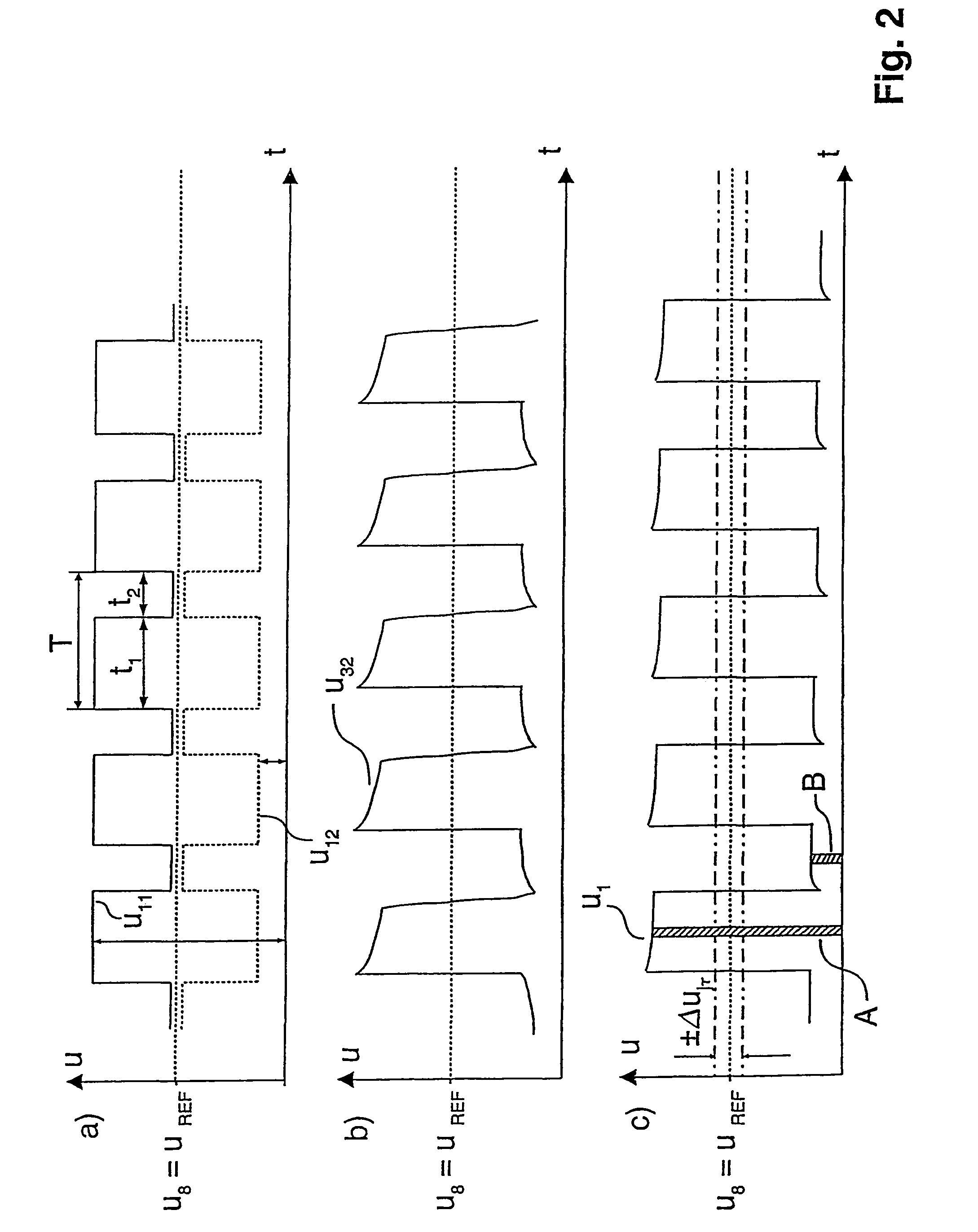
[0024]As regards a particularly satisfactory temperature compensation, the microprocessor or microcomputer could compute the difference and the change of the mean value from the signals that are digitized by means of an A / D converter. In this connection, the change of the mean value would be proportional to the gradient temperature. For improving the accuracy of the output signal, it would also be possible to use the digitized signals for averaging.

Problems solved by technology

Circuit arrangements of this type are problematic, in particular to the extent that they make great demands on all structural elements of the circuit arrangement.
Furthermore, the very complicated layout of the circuit arrangement is a problem.
These two aspects together are the reason for the often very high price of such a circuit arrangement, which remains high, even when the circuit arrangement is made as an integrated component in large quantities.
The known circuit arrangements are also problematic to the extent that the technical properties are often subjected to considerable limitations by the occurrence of phase shifts, phase rotations, and nonlinear distortions of the bridge output voltage, which often prevail as a result of the complex impedances of the sensor, and by the occurring nonlinearities of the unbalanced bridge circuit.
Thus, for example, higher harmonics that are generated by nonlinear effects in the ferromagnetic circuit of the sensor, and the quadrature component limit the resolution of the entire arrangement.

Method used


Image

  • Circuit arrangement and method for controlling and evaluating signal detectors
  • Circuit arrangement and method for controlling and evaluating signal detectors
  • Circuit arrangement and method for controlling and evaluating signal detectors

Examples


Embodiment Construction

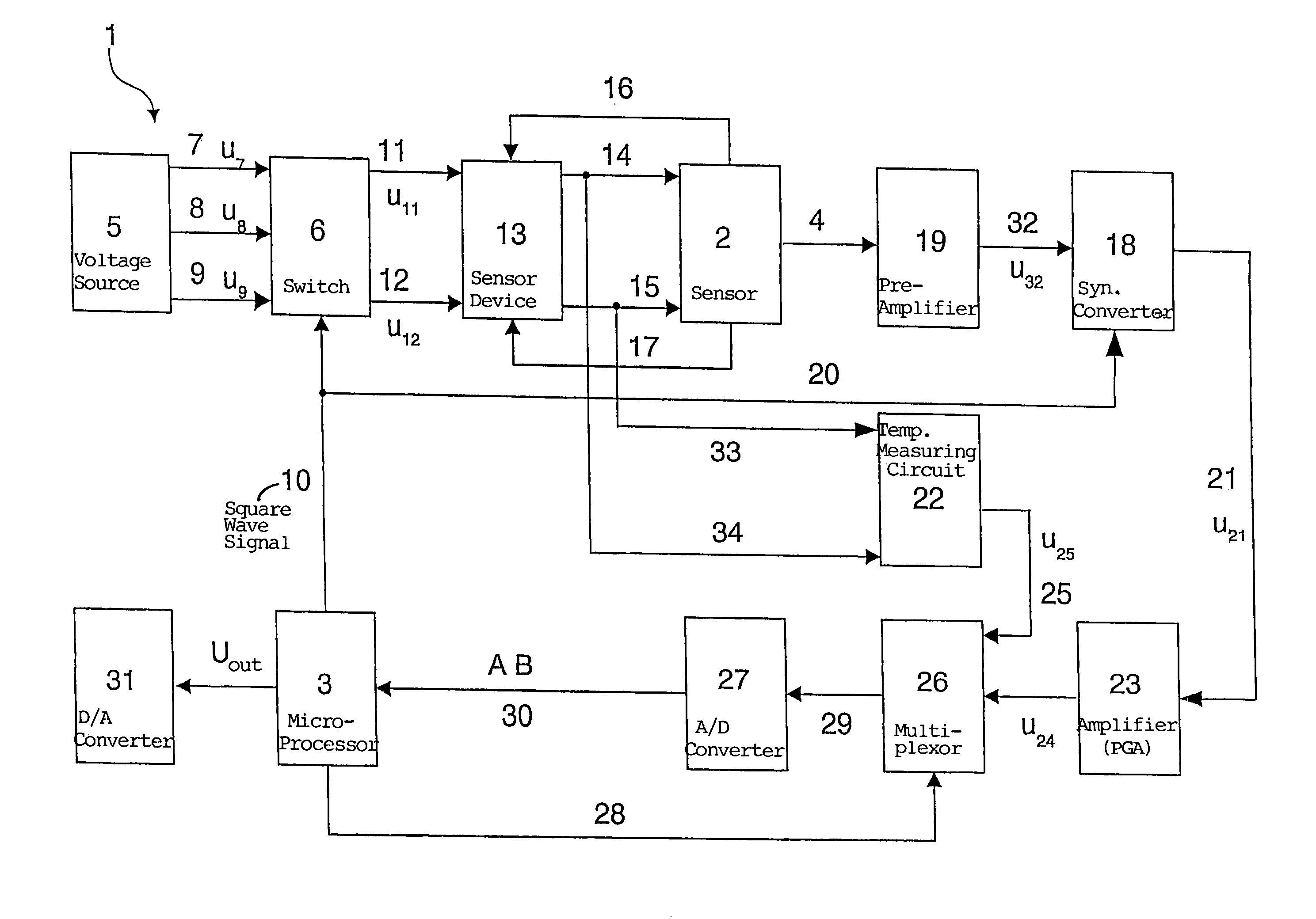
[0032]A circuit arrangement 1 for controlling sensors and evaluating their signals comprises a sensor 2 for acquiring mechanical quantities. In the present embodiment, the sensor 2 is an eddy current sensor.

[0033]In accordance with the invention, the measuring signal, the absolute temperature, and the gradient temperature of the sensor 2 can be simultaneously acquired, preferably by a microprocessor 3. In addition, it is possible to compensate at the same time the dependency of the measuring signal on the absolute temperature and the gradient temperature by means of the microprocessor 3.

[0034]The sensor 2 comprises two impedances Z1 and Z2. The temperature-dependent changes of the impedances Z1 and Z2 can be measured by means of the complex and the ohmic input resistance of sensor 2. The measuring signal is applied at the output of the sensor 2 to a line 4.

[0035]Three voltages u7, u8, and u9 can be generated by means of a source of voltage 5 and a switch 6. The switch 6 is a control...


PUM

PropertyMeasurementUnit
mechanicalaaaaaaaaaa
absolute temperatureaaaaaaaaaa
temperatureaaaaaaaaaa

Abstract

A circuit arrangement (10) for activating a sensor and evaluating its signals, in particular for parametric sensors with complex impedances. The circuit arrangement comprises at least one sensor (2) for acquiring mechanical data. In order to minimize or largely prevent temperature caused disturbances in a constructionally simple layout, the measuring signal, the absolute temperature, and the gradient temperature of the sensor (2) are acquired simultaneously, preferably by means of a microprocessor or microcomputer (3). A corresponding method for activating sensors and evaluating their signals is also described.

Description

CROSS REFERENCE TO RELATED APPLICATION[0001]This is a continuation of copending international application No. PCT / DE01 / 03032, filed 8 Aug. 2001 and designating the U.S.BACKGROUND OF THE INVENTION[0002]The invention relates to a circuit arrangement for activating sensors and evaluating their signals, in particular for parametric sensors with complex impedances, the circuit arrangement comprising at least one sensor for acquiring mechanical quantities. The invention further relates to a method for activating sensors and evaluating their signals, in particular parametric sensors with complex impedances, wherein at least one sensor acquires mechanical quantities.[0003]Circuit arrangements for activating sensors and evaluating their signals have been known from practice for a long time. Known circuit arrangements for activating sensors and evaluating their signals with complex impedances, for example, differential and nondifferential, inductive or capacitive sensors, such as linear varia...

Claims


Application Information

Patent Timeline
Patent Type & Authority Patents(United States)
IPC IPC(8): G01K1/00G01K11/00H03K17/94G01D3/036
CPCG01D3/036
Inventor MEDNIKOV, FELIXSELLEN, MARTINWISSPEINTNER, KARL
Owner MICRO EPSILON MESSTECHNIK GMBH & CO KG
Learn More