
Method for implanting a laminoplasty

a technology of laminoplasty and implanting method, which is applied in the field of spinal cages useful in laminoplasty surgery, can solve the problems of increased medical costs, pain, and weakness in arms and/or legs, and achieve the effects of improving the quality of li

Inactive Publication Date: 2006-02-14
DEPUY SPINE INC (US)
View PDF28 Cites 126 Cited by
  • Summary
  • Abstract
  • Description
  • Claims
  • Application Information

AI Technical Summary

Benefits of technology

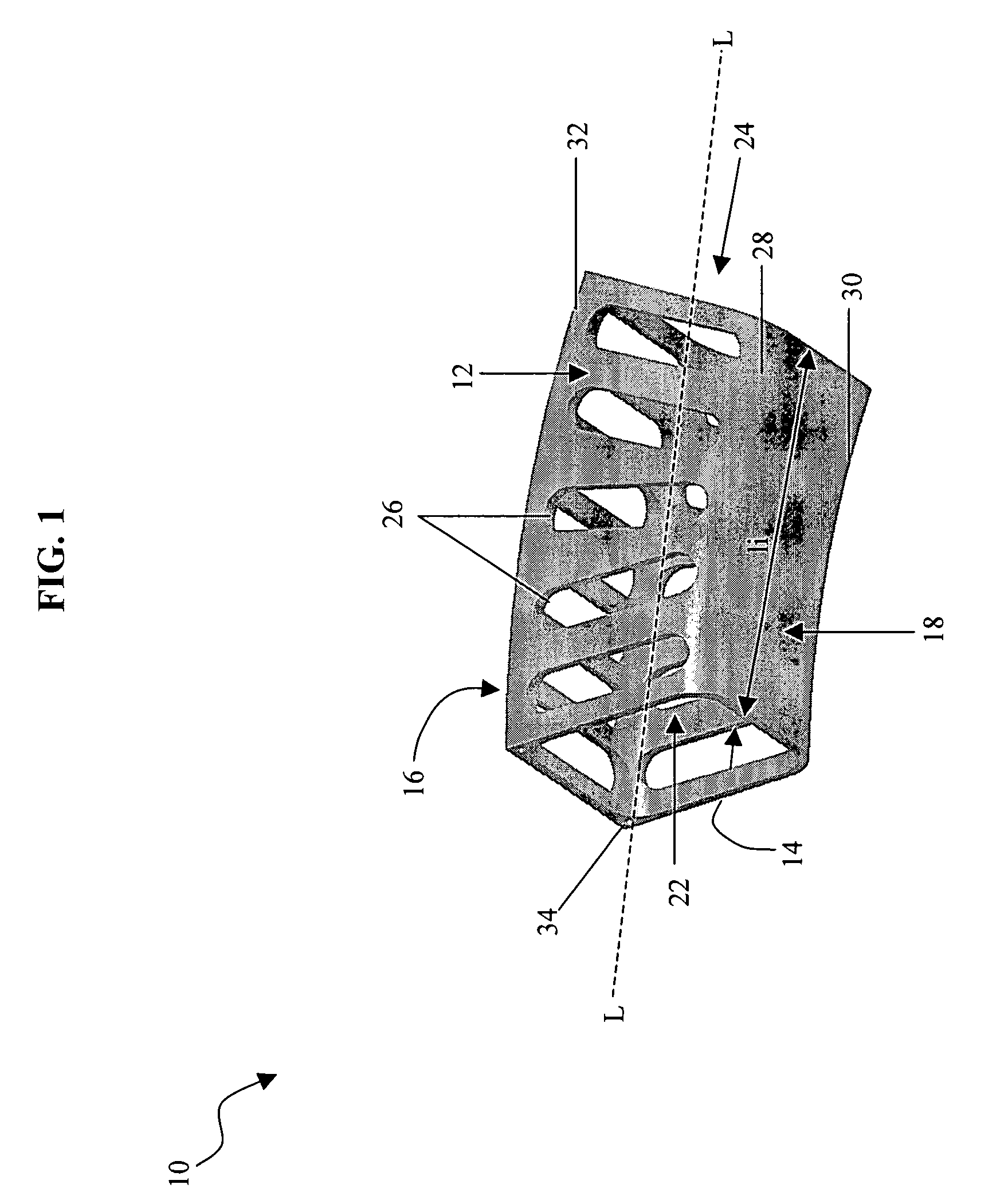
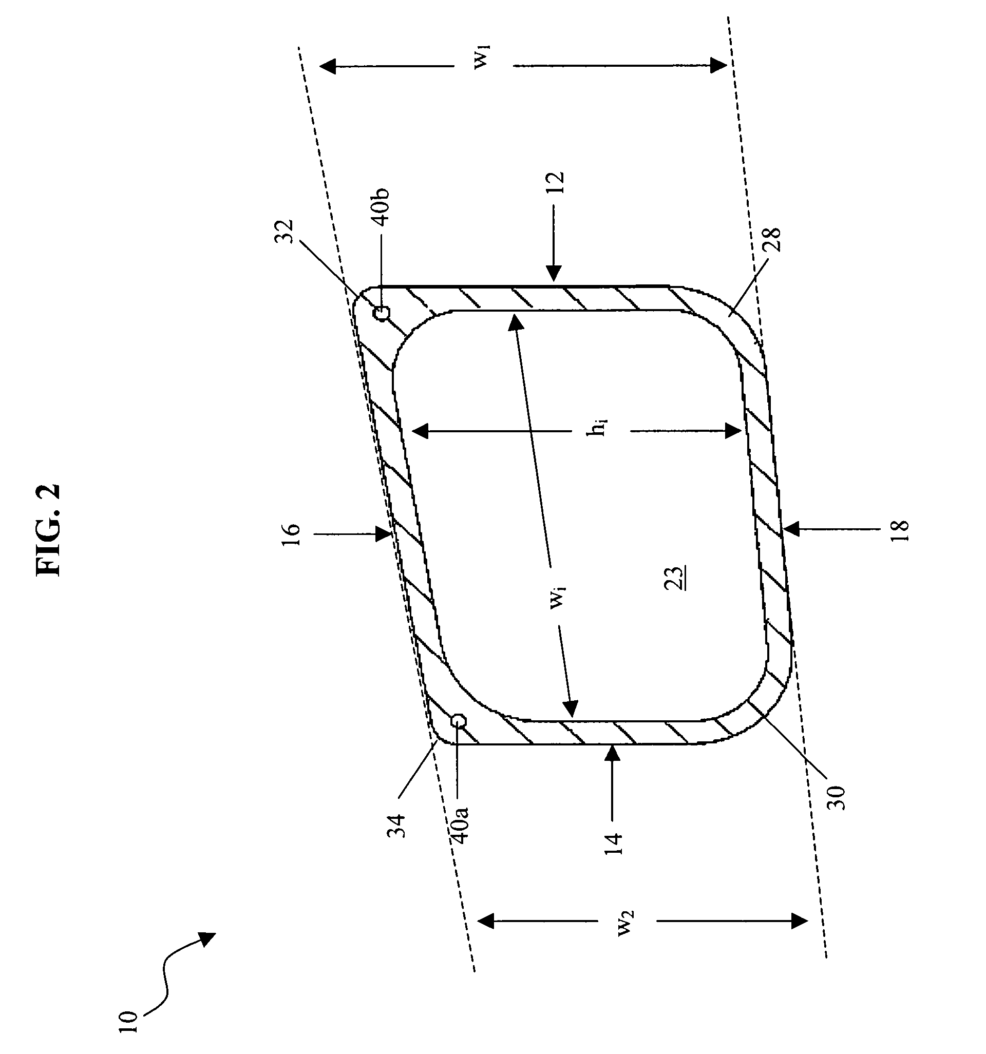
[0010]In another embodiment, the anterior side of the implant includes a first edge mated to the cephalad side and a second edge mated to the caudal side. Preferably, the first and second edges of the anterior side are substantially rounded. The anterior side of the elongate body can also be curved along the longitudinal axis such that an outer surface of the anterior side is concave. The rounded edges and the curved anterior side prevent potential abrasion or damage to tissue surrounding the implant, and provide additional space for the spinal cord in the spinal canal. The entire elongate body can also be curved along the longitudinal axis such that an outer surface of the anterior side is concave, and an outer surface of the posterior side is convex. That is, the planes defined by the first and second open ends are converging. This can be effected by designing the elongate body with the posterior side being longer than the anterior side.
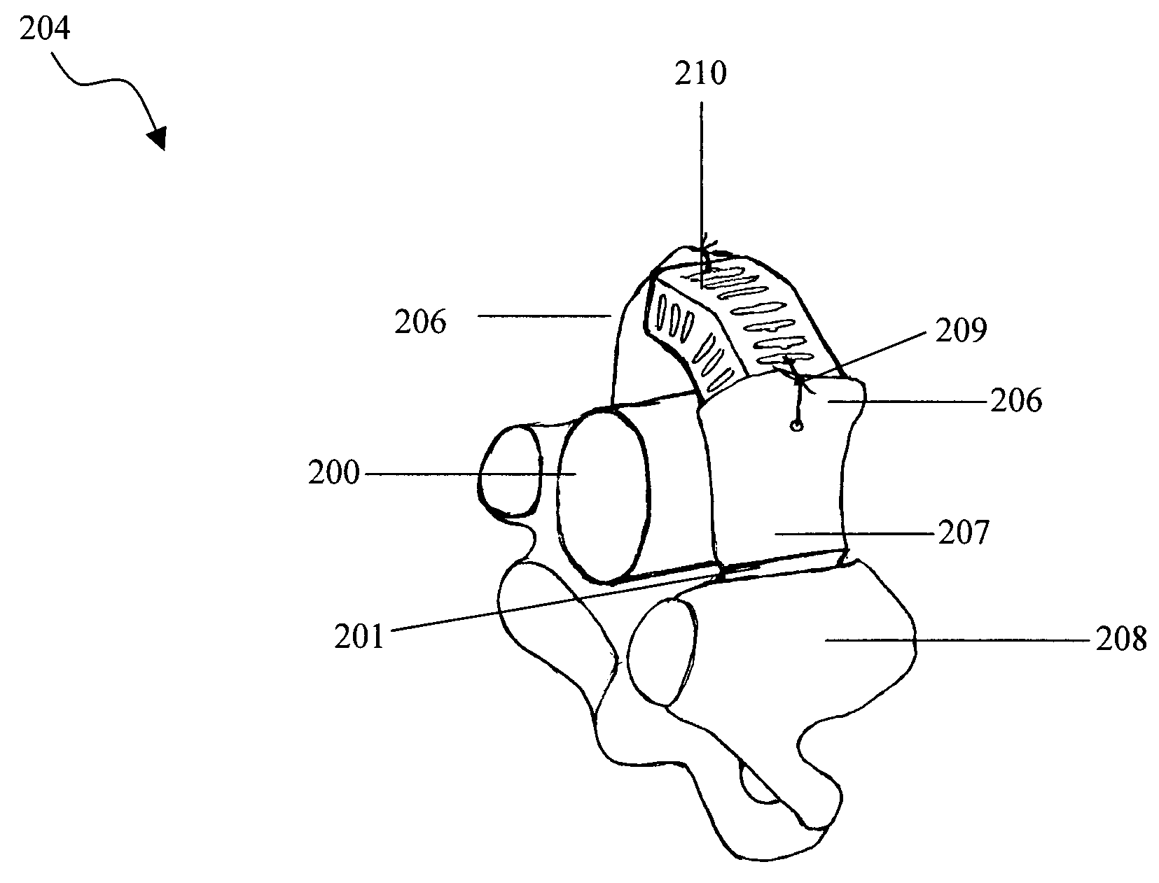
[0012]In another embodiment, the elongate body includes first and second halves positioned on opposed sides of a midpoint of the body. The first and second halves are preferably angled with respect to one another, such that the implant is bent at the midpoint. The bend is effective to provide additional space for the spinal cord within the spinal canal.
[0014]In yet another embodiment of the present invention, a medical implant device is provided having a hollow elongate body including a longitudinal axis, opposed cephalad and caudal sides, and opposed posterior and anterior sides adjacent to the cephalad and caudal sides. The cephalad side, caudal side, posterior side, and anterior side define an inner lumen having opposed first and second open ends. The implant further includes a fixation element receiving member mated to the posterior side of the implant, adjacent the first open end. The fixation element receiving member extends at an angle with respect to the longitudinal axis and is effective to receive a fixation element for attaching the implant to a bone structure.

Problems solved by technology

Spinal stenosis is the narrowing of the spinal cord canal, and can result in pain, weakness in arms and / or legs, and unsteadiness in the gait.
While these devices have proven effective, they can be difficult to implant, resulting in increased medical costs.
Moreover, the devices do not have a substantially low-profile, and thus can potentially cause damage to surrounding tissue and / or to the spinal cord.
The devices are also not designed to restore the natural dynamics of the cervical spine, and thus can cause discomfort to the patient.

Method used


Image

  • Method for implanting a laminoplasty
  • Method for implanting a laminoplasty
  • Method for implanting a laminoplasty

Examples


Embodiment Construction

[0025]The present invention provides a medical implant device for use in spinal surgery, and more preferably for use in laminoplasty surgery. The implant is a cage-like member having a generally hollow, elongate body with open ends. The implant can be adapted for use in a variety of applications, but is preferably used to maintain the position of vertebra after midline or open door laminoplasty surgery. The implant is particularly advantageous in that it is easy to implant, it will allow for permanent bony incorporation when used with bone growth promoting materials, it will allow for muscle re-attachment, it will restore the natural dynamics of the cervical spine, and it has a substantially low-profile to avoid or prevent damage to surrounding tissue.

[0026]FIGS. 1 and 2 illustrate one embodiment of an implant 10 according to the present invention. The implant 10 can have a variety of shapes and sizes, but preferably has a size and a geometry that enables it to be positioned in a bi...


PUM


Abstract

A medical implant device for use in spinal surgery, and more preferably for use in laminoplasty surgery is provided. The implant is a cage-like member having a generally hollow, elongate body with open ends. The implant is formed from a generally hollow, elongate body having four sides: opposed cephalad and caudal sides, and opposed posterior and anterior sides adjacent to the cephalad and caudal sides. The four sides extend along a longitudinal axis, and define an inner lumen extending between opposed first and second open ends.

Description

CROSS-REFERENCE TO RELATED APPLICATIONS[0001]This application is a continuation of application Ser. No. 10 / 260,329, filed Sep. 30, 2002, now U.S. Pat. No. 6,712,852 entitled “Laminoplasty Cage,” which is hereby incorporated by reference in its entirety.FIELD OF THE INVENTION[0002]The present invention relates to spinal implant device, and more particularly to spinal cages useful in laminoplasty surgery.BACKGROUND OF THE INVENTION[0003]Spinal stenosis is the narrowing of the spinal cord canal, and can result in pain, weakness in arms and / or legs, and unsteadiness in the gait. For mild conditions, conservative treatment may be sufficient. When symptoms are severe or progressive, however, cervical laminoplasty surgery may be required to enlarge the spinal canal to relieve compression of the spinal cord. Common indications which give rise to a need for laminoplasty surgery include stenosis of the spinal canal, ossification of the posterior longitudinal ligament (OPLL), and spondylotic m...

Claims


Application Information

Patent Timeline
IPC IPC(8): A61F2/44A61B17/58A61B17/70A61F2/00A61F2/28A61F2/30A61L27/00
CPCA61B17/7071A61F2/4455A61F2002/3008A61F2002/30578A61F2002/30777Y10S606/912A61F2002/448A61F2250/0098Y10S606/907Y10S606/91A61F2002/4475A61F2002/30593A61F2/44
Inventor CHUNG, JAE-YOONMICHIELLI, MICHAEL CARL
Owner DEPUY SPINE INC (US)
Learn More