Method and system for displaying cross-sectional images of a body
a cross-sectional image and body technology, applied in the field of medical procedures, can solve the problems of difficult comprehension of images, inability to teach the generation and use of non-overlapping images, and inability to use ultrasound to direct the imaging plane. , to achieve the effect of more interpretable cross-sectional images
- Summary
- Abstract
- Description
- Claims
- Application Information
AI Technical Summary
Benefits of technology
Problems solved by technology
Method used
Image
Examples
example 1
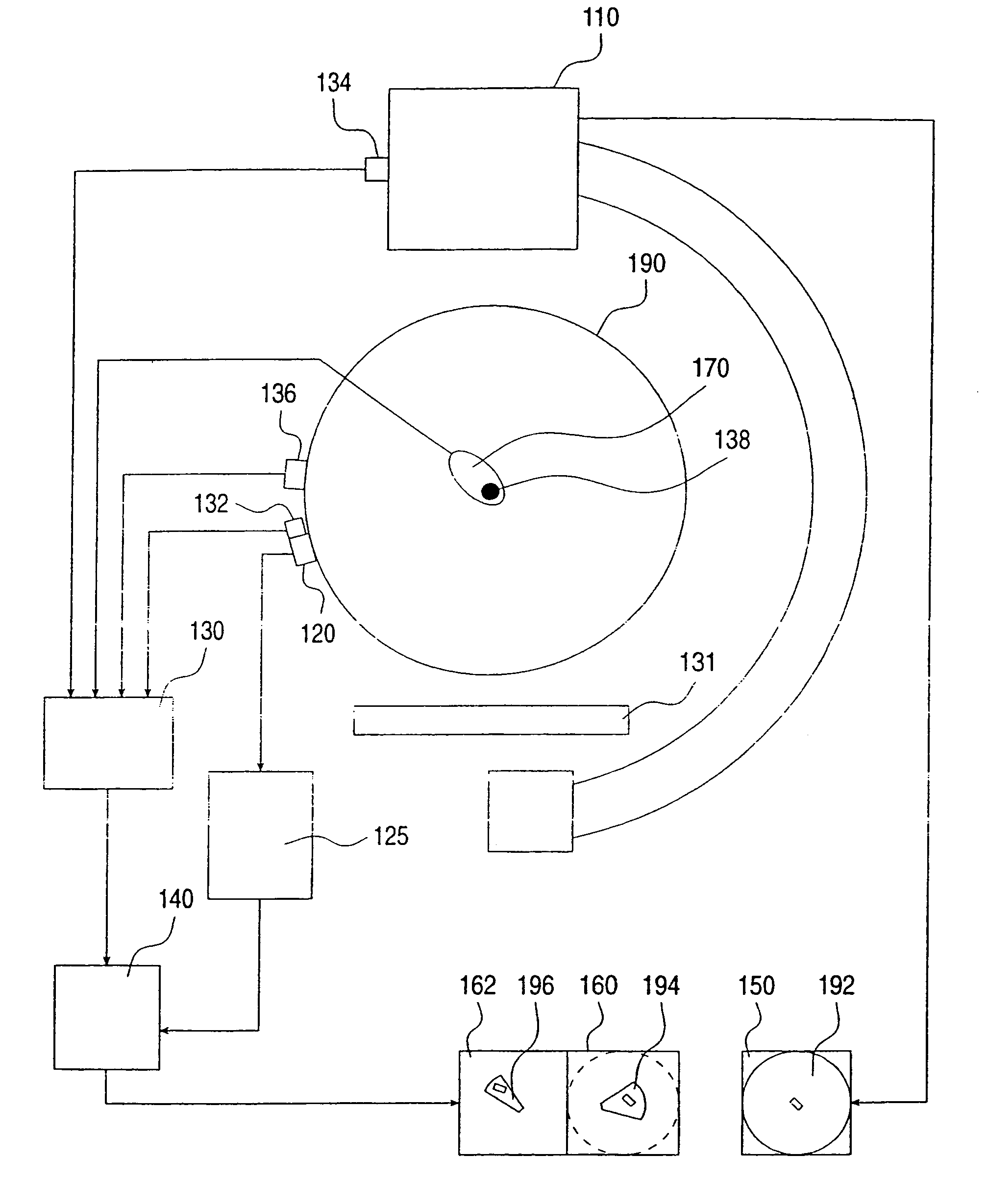
[0054]FIG. 1 shows a system having a fluoroscope 110 which is used as a primary imager. Its output image 192 is displayed on a monitor 192. A single plane ultrasound transducer 120 is used as a secondary imager. Transducer 120 may be of an external type, imaging from the skin of the patient, or of an internal type (such as TEE or IVUS or ICUS), imaging from the interior of the patient's body. In any case, transducer 120 is moving in free hand. A first locating sensor 134 is attached to the frame of the fluoroscope. A second locating sensor 132 is attached to, or embedded into, transducer 120. A third locating sensor 138 is embedded into a treatment-applying probe 170. A fourth locating sensor 136 is attached to the body of the patient (it may also be located within the body). A locating system 130 feeds three low frequency current signals to antennae 131. All four locating sensors 132, 134, 136, 138 are sensing the induced electromagnetic fields, and the sensed signals are fed to sy...
example 2
[0061]This Example provides a system similar to that described under Example 1 hereinabove, except that ultrasound system 125 and ultrasound transducer 120 form a real-time 3D ultrasound imaging system. Computer 140 is programmed to produce a 3D rendered model from the ultrasound data. The rendered picture 194 is produced as if seen from the direction of the PLOS, to be displayed on display 160. The rendered picture 196 is may additionally be produced as if seen from a direction perpendicular to the PLOS, to be displayed on display 162.
example 3
[0062]FIG. 3 shows yet another system in accordance with the teachings of the present invention having a fluoroscope, which is again used as a primary imaging device. A fluoroscopic image 392 is displayed on display 350. CT, MRI or 3D-ultrasound device serves as a secondary imaging device. However, as opposed to the former two examples, the images thereof were previously-taken. Locating system 330 feeds low frequency current signals to antennae 331. Locating sensor 334 senses the electromagnetic signals that are induced by the antennae and feeds these signals to locating system 330. Locating system 330 calculates in 6 DOF the location and orientation of the fluoroscope relative to a reference system of coordinates that is defined by, for example, antennae 331. A locating sensor 338 implemented into a probe 370 also senses the electromagnetic fields, feeds them to system 330, so that the location and orientation in 6 DOF of probe 370 is also calculated. The resulting locations and or...
PUM
 Abstract
Description
Claims
Application Information
 - Generate Ideas
- Intellectual Property
- Life Sciences
- Materials
- Tech Scout
- Unparalleled Data Quality
- Higher Quality Content
- 60% Fewer Hallucinations
Browse by: Latest US Patents, China's latest patents, Technical Efficacy Thesaurus, Application Domain, Technology Topic, Popular Technical Reports.
© 2025 PatSnap. All rights reserved.Legal|Privacy policy|Modern Slavery Act Transparency Statement|Sitemap|About US| Contact US: help@patsnap.com


