
Tilt mirror controlling apparatus and method

a technology of tilt mirror and control apparatus, which is applied in the direction of optics, instruments, optics, etc., can solve the problems of difficult control of significant non-linearity due to voltage square term, non-linearity of electrostatic capacity, and often becomes a problem, etc., to achieve stable control, facilitate control of target angle and various parameters, and stable angle response

Active Publication Date: 2006-02-07
FUJITSU LTD
View PDF11 Cites 11 Cited by
  • Summary
  • Abstract
  • Description
  • Claims
  • Application Information

AI Technical Summary

Benefits of technology

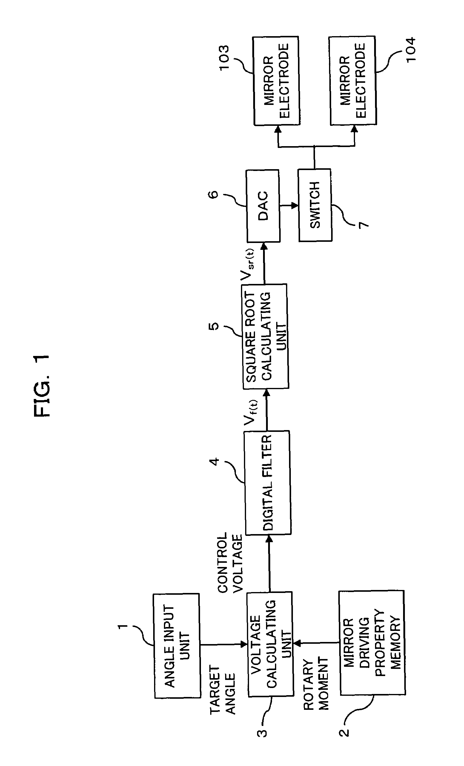
[0040]In accordance with the present invention, square root calculation processing is digitally performed on a waveform of voltage from which an resonance frequency component, due to an angle response of the tilt mirror, has been removed, so that the non-linearity of mirror rotation angles versus control voltages (feed forward control) can be compensated for, thus realizing a high-speed, stable mirror control. In particular, since the filter and the square root calculating unit are digitalized, it is possible to facilitate control of the target angle and various parameters such as driving property information of the tilt mirror, thereby realizing stable control even with a downsized apparatus.
[0041]Further, when controlling the tilt mirror, whose tilt angle is controlled by electrostatic attraction, table calculation processing (voltage approximation) is performed on the control signal to compensate for the non-linearity of electrostatic capacities versus mirror tilt angles. As a result, linear control of the tilt mirror becomes virtually available, and mirror control is realized such that a residual resonance frequency due to the tilt mirror is sufficiently suppressed even by a downsized control apparatus and such that a high-speed and stable angle response is available.
[0042]Furthermore, by controlling a pulse wave form appearing in initial part of a tilt mirror control signal, it is possible to compensate for waveform distortion of such a pulse waveform, so that efficient mirror control is attained such that a speedy and stable angle response is realized immediately after initiation of the control.

Problems solved by technology

When controlling such electrostatic force-actuated tilt mirrors, non-linearity of electrostatic capacity often becomes a problem.
Although the non-linearity of electrostatic capacity can be suppressed by improving the construction of the electrodes or by limiting an action range (angle range) of the tilt mirror 102, a significant non-linearity due to the voltage squared term is difficult to control.
In a case where MEMS tilt mirrors (hereinafter simply called MEMS mirrors) are to be controlled, their minuteness makes it difficult to incorporate any mirror angle detecting units therein.
In particular, since a number of MEMS mirrors are required to form an optical mirror switch, such angle detecting units prepared, one for each of the MEMS mirrors, will affect practicality and cost performance of the system.
In addition, even if such feedback control is successfully applied, thus allowing the tilt mirrors to settle down into their ideal angles sooner than they do by natural attenuation, a significant divergence, if any, from an ideal voltage characteristic delays the settlement.
In addition, since the current-voltage characteristic of a diode is susceptible to temperature, and since variations among individual components need to be considered, the adjustment is required to be performed separately on each of the control objects.
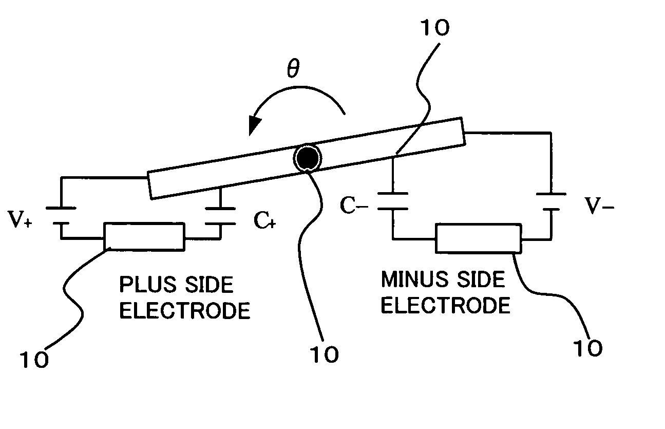
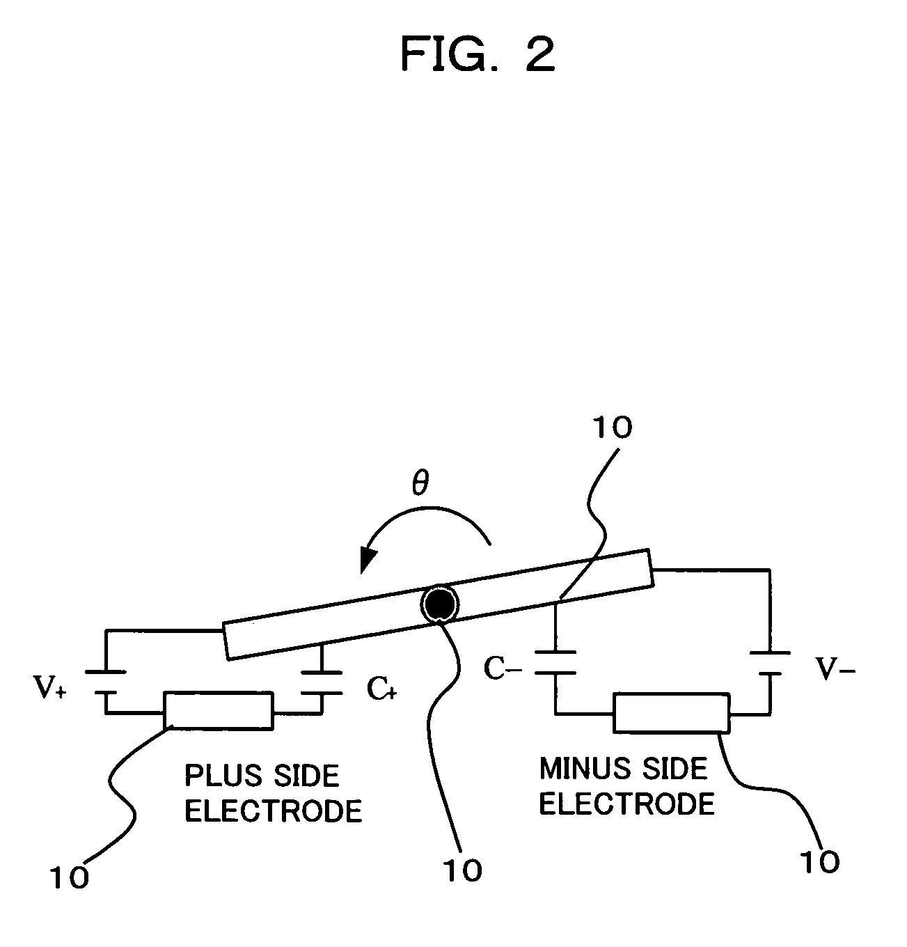
Further, even if square root calculation is applied, it is still impossible to compensate for effects of the non-linearity [angular dependency of a value that is obtained by partially differentiating (angular differentiation) an electrostatic capacity C with respect to a mirror rotation angle θ] of electrostatic capacity against mirror rotation angles.
Thus, a residual resonance frequency cannot be sufficiently suppressed.
It is thus impossible to solve the foregoing problems using these technologies.

Method used


Image

  • Tilt mirror controlling apparatus and method
  • Tilt mirror controlling apparatus and method
  • Tilt mirror controlling apparatus and method

Examples


first embodiment

[0058][1]

[0059]FIG. 1 schematically shows a tilt mirror control apparatus according to a first embodiment of the present invention. The control apparatus, for example, controls a tilt angle of the tilt mirror 102 already described with reference to FIG. 13. In the present embodiment, as shown in FIG. 1, the control apparatus has an angle input unit 1, a mirror driving property memory 2, a voltage calculating unit 3, a digital filter 4, a square root calculating unit 5, a digital to analog converter (DAC) 6, and a switch 7. Items 103 and 104 are electrodes (a plus-side electrode and a minus-side electrode) placed under the tilt mirror 102. Those electrodes are symmetrically disposed with respect to a rotation axis (torsion bar) 101 (see FIG. 13) of the tilt mirror 102.

[0060]The angle input unit 1 inputs a target tilt angle of the tilt mirror 102 as a parameter; the mirror driving property memory 2 stores, in advance, information (hereinafter called “driving property information”) abo...

second embodiment

[0082][2]

[0083]A second embodiment of the present invention aims to realize mirror controlling even speedier and more stable than the above first embodiment. In mirror control according to the first embodiment, there is no denying that it is still difficult to completely compensate for effects given from the non-linearity [angular dependency of the following equation (C-1)

∂C / ∂θ  (C-1)

in the right side of the foregoing formula (1)] of electrostatic capacities against mirror rotation angles (tilt angles). It thus cannot be said that a residual resonance frequency is suppressed truly sufficiently.

[0084]This is because, in the first embodiment (or the conventional art), α, expressed by the formula (A-10), is regarded as a constant. As shown in FIG. 5, for example, there appears deviation (see the broken line 13 and the solid line 14) between the angular differentiation of the mirror electrostatic capacity against the mirror rotation angle and an ideal characteristic. In the second embod...

third embodiment

[0100][C]

[0101]The foregoing formula (C-4) can be expressed as θα⁡(θ)=θmaxVcmax⁢Vcα⁡(θmaxVcmax⁢Vc)(D⁢-⁢1)

Thus, it can be approximated as θ=θmaxVcmax⁢Vc(D⁢-⁢2)

That is, θ∝Vc. This relational expression goes for where θc is obtained. In the above example, however, a non-linear rate of change in capacity is compensated for by assuming that “the mirror 102 is in a state of equilibrium” [using the foregoing kinetic equations (A-2) and (A-3), where the equations (A-4) and (A-5) are satisfied and where θ>0 and V>0]. Thus, if a voltage such that the equilibrium is disturbed is applied, or if the voltage is changed so fast that the mirror 102 cannot respond thereto in changing its angles, the above approximation cannot be established.

[0102]This causes distortion of an electrostatic torque, thereby inducing an occurrence of resonance. In particular, when high-speed step driving is performed, a short-pulse-like voltage needs to be initially applied, resulting sometimes in marked torque distorti...


PUM


Abstract

The apparatus controls a tilt angle of a tilt mirror in high speed with high stability, realizing non-linearity compensation. The apparatus includes: a control signal producing unit, which produces a control signal, for feed-forward controlling of the mirror into a target tilt angle, based on a parameter that determines the target tilt angle; a digital filter for removing a resonance frequency component, which is caused by an angle response of the tilt mirror, in the control signal, which is produced by the control signal producing unit; and a square root calculating unit for performing digital square-root calculation so that non-linearity of the control signal, from which the resonance frequency component has been removed, is compensated for.

Description

BACKGROUND OF THE INVENTION[0001]1. Field of the Invention[0002]The present invention relates to a method and an apparatus for controlling tilt mirrors, which have been used in optical cross connects, optical add-drop multiplexers, optical routers, etc., in a WDM (Wavelength-Division Multiplexing) system which realizes high-speed, large-capacity data transmission.[0003]2. Description of the Related Art[0004]FIG. 13 is a perspective view in schematic form depicting a previously known optical tilt mirror that is actuated by electrostatic force. This electrostatic force-actuated tilt mirror has a tilt mirror 102 that can rotate about a torsion bar 101 and electrodes (underneath electrodes), 103 and 104, placed under the tilt mirror 102. By changing a voltage applied to the electrodes, 103 and 104, an electrostatic attraction given to the tilt mirror 102 is changed, thereby varying an angle at which the tilt mirror 102 is tilted. Note that such an electrostatic force-actuated tilt mirro...

Claims


Application Information

Patent Timeline
Patent Type & Authority Patents(United States)
IPC IPC(8): G02B26/08G02B26/00G02B26/10
CPCG02B26/0841
Inventor YAMABANA, TETSUJIMORI, KAZUYUKI
Owner FUJITSU LTD
Learn More