
Arbitration method for a source strobed bus

Inactive Publication Date: 2006-01-31
MICRON TECH INC
View PDF26 Cites 63 Cited by
  • Summary
  • Abstract
  • Description
  • Claims
  • Application Information

AI Technical Summary

Benefits of technology

[0006]The invention provides an arbitration method in a source strobed bus architecture that minimizes a number of integrated circuit (IC) pins. Arbitration between two devices requires only one pin and this pin can also be used for other purposes since information is time-multiplexed between the devices.
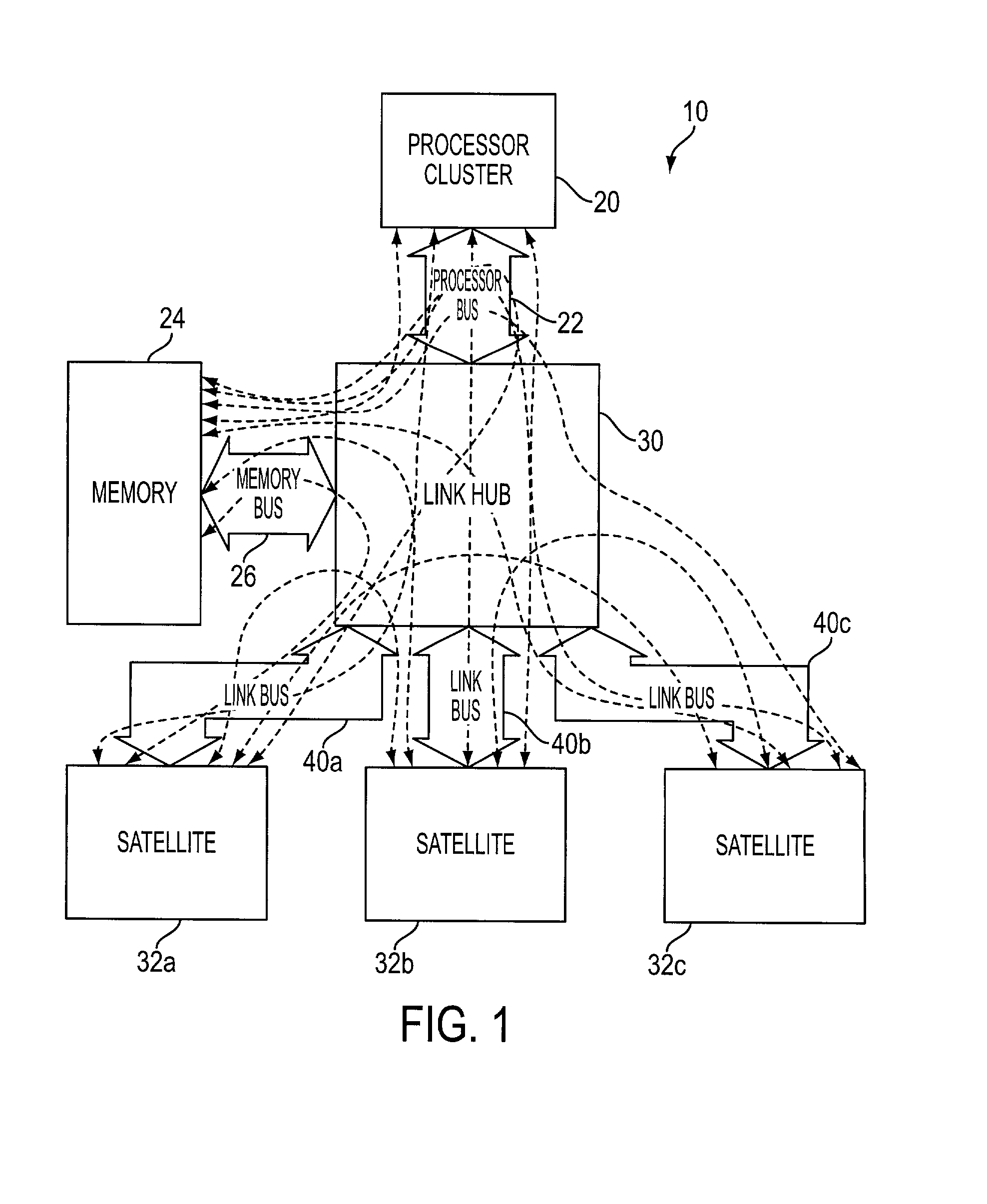
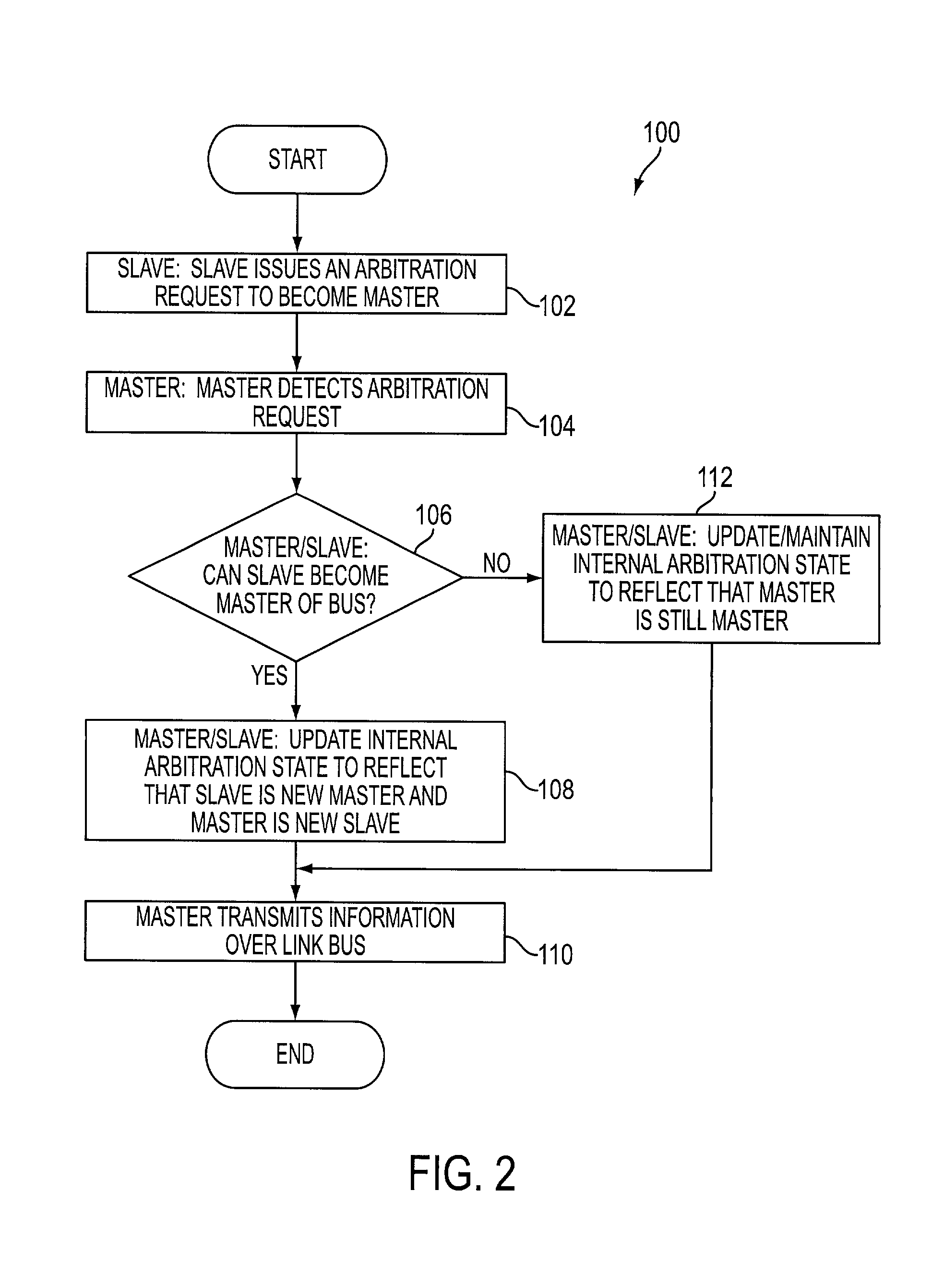
[0007]The above and other features and advantages are achieved by a hub based computer system having a central hub that communicates with a plurality of satellite devices over respective link buses. Each link bus is substantially the same and adheres to a predefined link bus protocol. The satellite devices are also connected to industry standard buses / devices and the central hub also communicates with a processor cluster and system memory over respective processor and memory buses. Thus, all components within the system are capable of communicating with each other through the hub. Each link bus includes a status line that allows each device connected to the same link bus to request control of the bus. The link bus protocol establishes a window in which the status signal may convey arbitration request information in a time-multiplexed manner. The protocol further includes a method of determining whether control of the bus can be transferred to a different device. Each device takes part in the decision process and thus, the arbitration method of the invention is decentralized. The invention dispenses with the need for a dedicated arbitration device, which substantially reduces costs and delays in the system.

Problems solved by technology

This dedicated arbitration device adds expense and delays to the system since an additional device is connected to, and communicating over, the bus.

Method used


Image

  • Arbitration method for a source strobed bus
  • Arbitration method for a source strobed bus
  • Arbitration method for a source strobed bus

Examples


Embodiment Construction

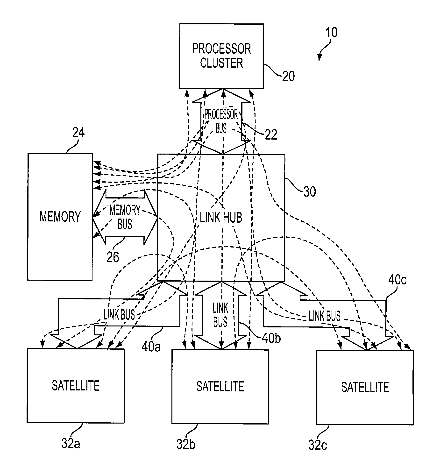
[0014]FIG. 1 is a hub based computer system 10 utilizing link buses 40a, 40b, 40c (collectively referred to herein as “link buses 40”) in accordance with an exemplary embodiment of the invention. The system 10 includes a processor cluster 20, a memory device 24, a link hub 30 and a plurality of satellite devices 32a, 32b, 32c (collectively referred to herein as “satellite devices 32”). The processor cluster 20 may contain one or many processor units. Although not required to practice the invention, if more than one processing unit is contained within the cluster 20, they are preferably identical to each other. The satellite devices 32 can be bridges or hubs to industry standard buses, such as e.g., PCI, PCI-X and AGP, or the devices 32 can be other components typically found in a computer system. The devices 32 can be connected to one or more I / O devices if so desired.

[0015]The link hub 30 is connected to the processor cluster 20 by a dedicated processor bus 22. The link hub 30 is c...


PUM


Abstract

A hub based computer system having a central hub that communicates with a plurality of satellite devices over respective link buses. Each link bus is substantially the same and adheres to a predefined link bus protocol. The satellite devices are also connected to industry standard buses / devices. The central hub also communicates with a processor and system memory over additional buses. Each link bus includes a status line that allows each device connected to the same link bus to request control of the bus. The link bus protocol establishes a window in which the status signal may convey arbitration request information in a time-multiplexed manner. The protocol further includes a method of determining whether control of the bus can be transferred to a different device. Each device takes part in the decision process and thus, the arbitration method of the invention is decentralized.

Description

FIELD OF THE INVENTION[0001]The invention relates to computer systems, and more particularly to an arbitration method for a source strobed computer bus.BACKGROUND OF THE INVENTION[0002]Several of today's computer system architectures employ a source strobed bus and method to transfer data between devices. In a typical source strobe architecture, the transmitting device transmits to the receiving device a clock signal / strobe and data. The strobe alerts the receiving device that valid data has been transmitted over the bus. Computer bus architectures such as AGP (accelerated graphics port), DDR SDRAM (double data rate synchronous dynamic random access memory), and RDRAM (Rambus random access memory) utilize source strobes in this manner.[0003]A source strobe data bus is an efficient mechanism for transferring large amounts of data on a minimum number of pins or connections between devices. In the typical source strobe computer architecture, one device connected to the source strobed b...

Claims


Application Information

Patent Timeline
IPC IPC(8): G06F13/00G06F13/368H04J3/02G06F13/36H04J3/00
CPCG06F13/368G06F13/36
Inventor PORTERFIELD, A. KENT
Owner MICRON TECH INC
Learn More