
Photographing lens

a technology of lens and image, applied in the field of photography lenses, can solve the problems of inability to provide satisfactory images and thin lenses, and achieve the effect of good optical characteristics

Active Publication Date: 2006-01-31
COPAL CO LTD
View PDF8 Cites 18 Cited by
  • Summary
  • Abstract
  • Description
  • Claims
  • Application Information

AI Technical Summary

Benefits of technology

[0010]The present invention has been made in view of the above problems, and an object of the present invention is to provide a small, thin, light, low-cost, and high-performance photographing lens that has a simple lens configuration, that prevents vignetting, and that can be included in an image pickup device having a high resolution of a million pixels or more mounted in a mobile telephones with a camera, such as a digital still camera or a digital video camera used in a device such as a portable telephone or a personal digital assistant, by properly determining the position of aspherical surfaces.

Problems solved by technology

However, since photographing lenses are provided for relatively low-resolution image pickup devices with approximately 100,000 pixels to 350,000 pixels, they cannot provide images of satisfactory quality.
In conventional image pickup devices, photographing lenses cannot be thin (the total length of the lens systems cannot be short) because of the limit of the light exit angle.

Method used


Image

  • Photographing lens
  • Photographing lens
  • Photographing lens

Examples


Embodiment Construction

[0039]Preferred embodiments of the present invention will be described below with reference to the attached drawings.

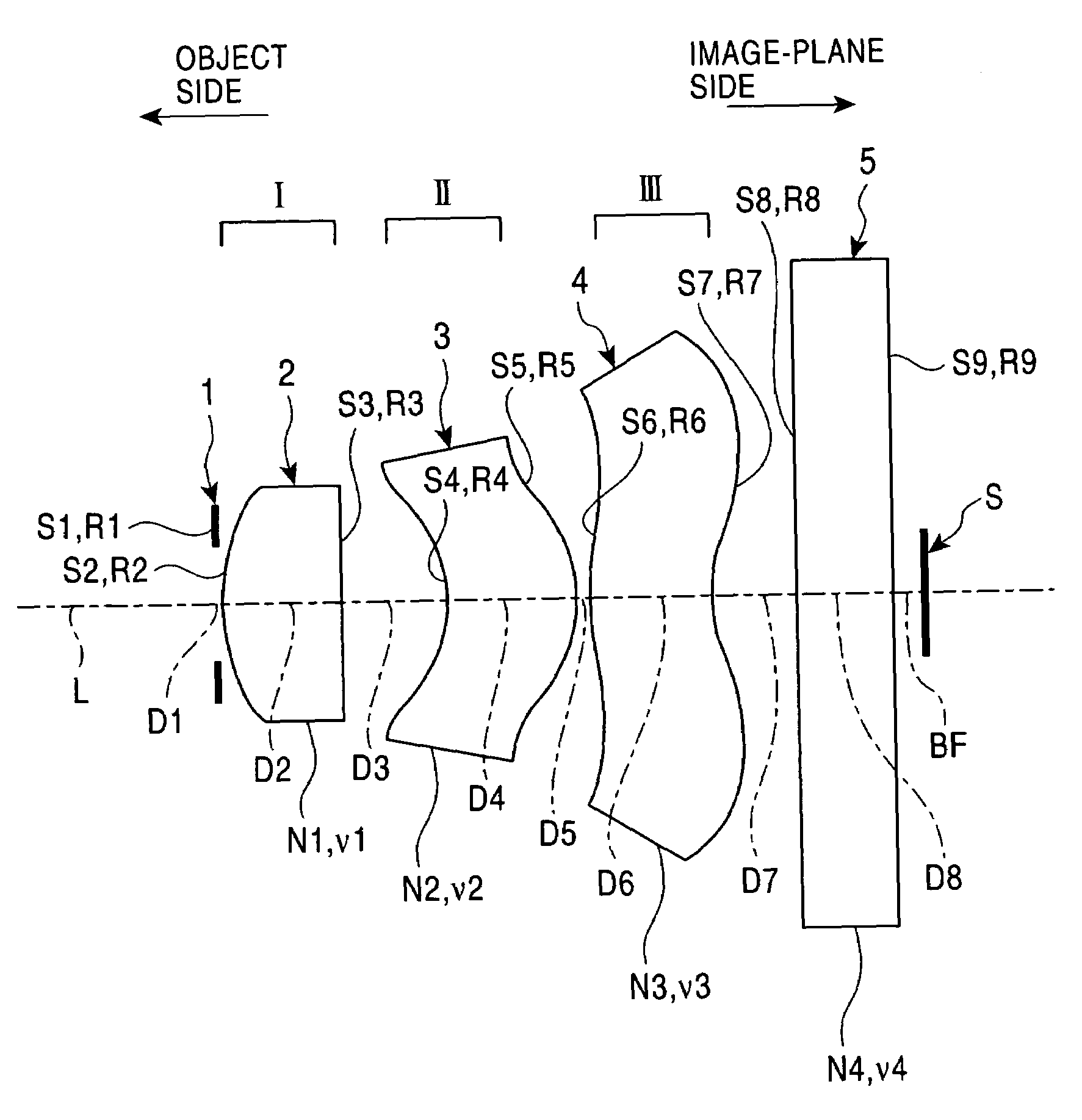
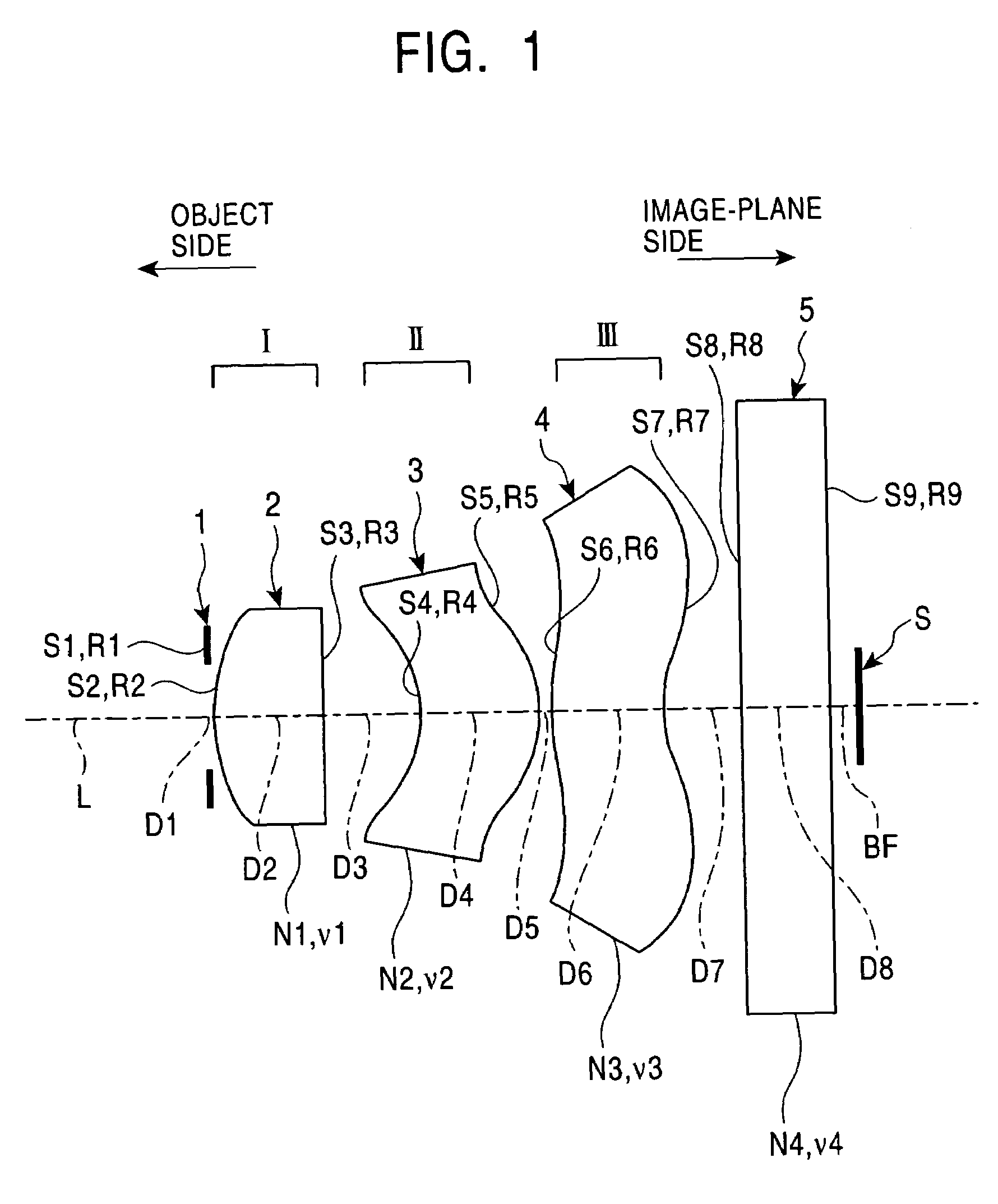
[0040]FIG. 1 shows the basic configuration of a photographing lens according to an embodiment of the present invention. In the photographing lens of the embodiment of the present invention, an aperture stop 1 having a predetermined aperture, a first lens unit I, a second lens unit II, and a third lens unit III are arranged in order from the object side toward the image-plane side, as shown in FIG. 1.

[0041]The first lens unit I is composed of a first lens 2 that has a positive refractive power and includes a convex surface facing toward the object side. The second lens unit II is composed of a second lens 3 that has a positive refractive power and includes a concave surface facing toward the object side. The third lens unit III is composed of a third lens 4 that has a negative refractive power and includes a convex surface facing toward the object side.

[0042]In this co...


PUM


Abstract

A photographing lens includes an aperture stop having a predetermined aperture, a first lens having a positive refractive power and a convex surface facing the object side, a second lens having a positive refractive power and aspherical surfaces on both sides, the object-side aspherical surface being concave, and a third lens having a negative refractive power and aspherical surfaces on both sides, the object side surface being convex. The aperture stop and the first, second, and third lenses are arranged in order from the object side toward the image-plane side. With such a three-unit, three element lens configuration, a proper back focus is ensured, aberrations are properly corrected, and the total lens length and thickness of the photographing lens are reduced. The photographing lens can be suitably applied to high-resolution image pickup devices with a million pixels or more.

Description

BACKGROUND OF THE INVENTION[0001]1. Field of the Invention[0002]The present invention relates to a photographing lens for use in mobile telephones with cameras, such as digital still cameras or video cameras that have an image-pickup device, such as a CCD, and that are provided in devices such as portable telephones, personal digital assistants (PDAs), and portable personal computers.[0003]2. Description of the Related Art[0004]A conventional photographing lens is included in an image pickup device, such as a CCD, in order to take moving images, for example, as in surveillance cameras. Surveillance cameras are mainly used to take moving images, and the number of pixels of an image pickup device used therein is relatively small. Therefore, the surveillance cameras do not need a lens system having a high optical performance.[0005]It has been pointed out that the quality of images taken by image pickup devices used in conventional surveillance cameras, video cameras, and the like is lo...

Claims


Application Information

Patent Timeline
IPC IPC(8): G02B9/12G02B13/18G02B13/00
CPCG02B9/12G02B13/0095G02B13/0035
Inventor TAKEUCHI, HOTAKAISHIKAWA, YOICHIABE, YASUHIKO
Owner COPAL CO LTD
Learn More