Color combining optical system, projection-type display optical system, projection-type image display apparatus, and image display system
a technology of color combining and optical system, which is applied in the direction of projectors, projectors, and picture reproducers using projection devices, etc., can solve the problems of increased noise of fans, increased sound during spraying cooling air, and increased light which must be absorbed by exit-side polarizing plates, etc., to reduce thermal problems, increase the effect of size and high brightness
- Summary
- Abstract
- Description
- Claims
- Application Information
AI Technical Summary
Benefits of technology
Problems solved by technology
Method used
Image


Examples
embodiment 1
[0021
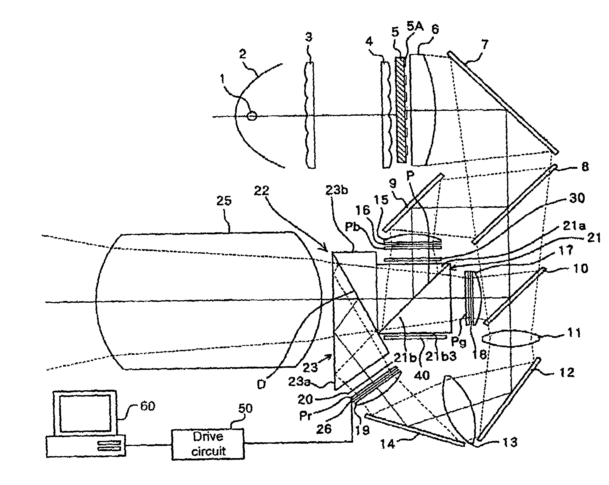
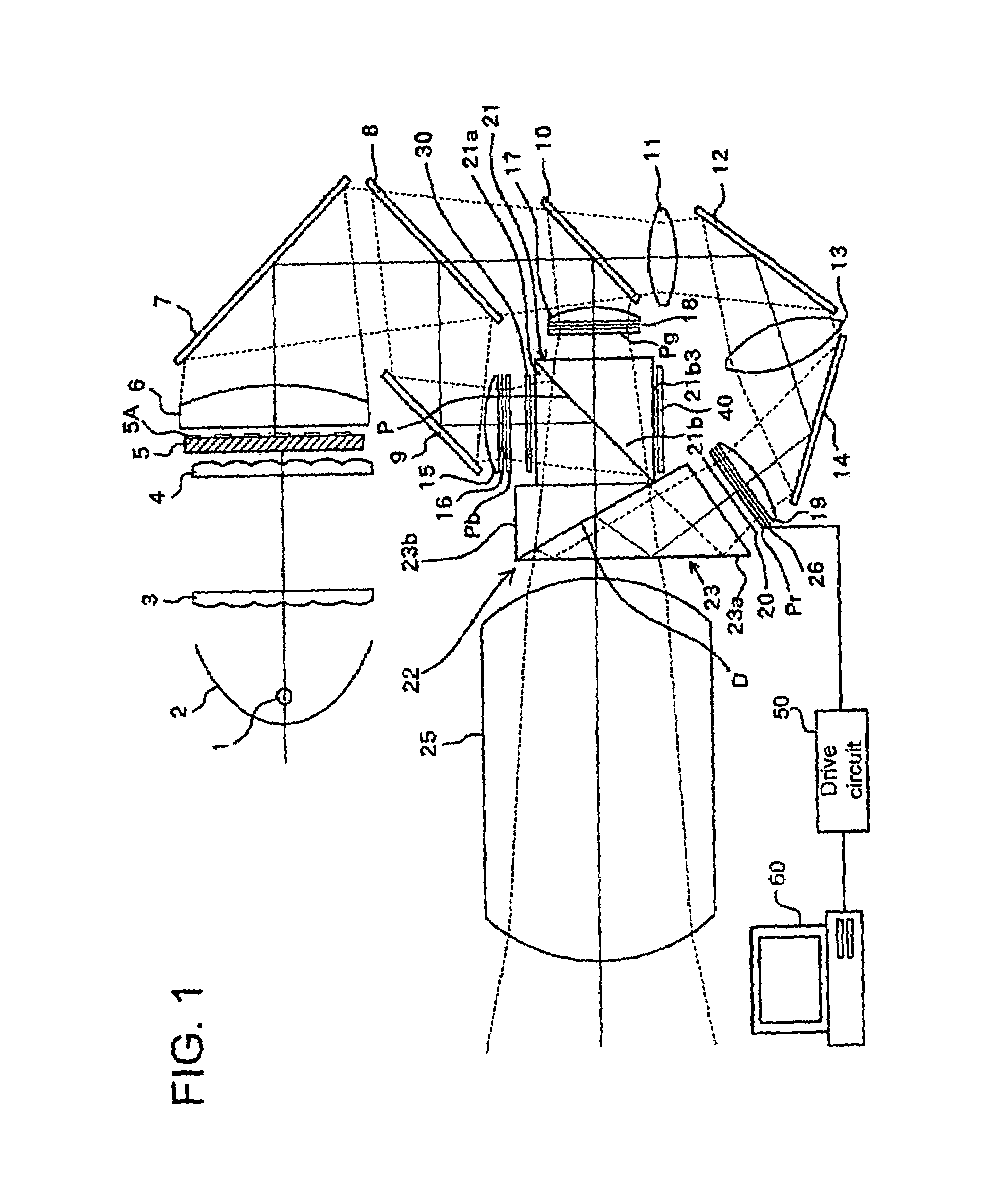
[0022]FIG. 1 shows a schematic structure of a liquid crystal projector (a projection-type image display apparatus) using a projection-type display optical system of Embodiment 1 of the present invention.
[0023]In FIG. 1, reference numeral 1 denotes a light source such as a super high-pressure mercury lamp. Reference numeral 2 denotes a reflector having a paraboloidal-shaped reflective surface (this may be an ellipsoidal shape), and a paraboloidal-shaped mirror is illustrated in the drawing.
[0024]A light flux emitted from the light source 1 is converted to an approximately parallel light by being reflected by the reflector 2 and is made incident into a first fly-eye lens 3. The first fly-eye lens 3 is structured by arranging a plurality of rectangular lenses (convex lenses) having a positive optical power on a flat plate.
[0025]Reference numeral 4 denotes a second fly-eye lens into which a light flux emerged from the first fly-eye lens 3 is made incident, and this is structured by...
embodiment 2
[0067
[0068]FIG. 3 shows a schematic structure of a liquid crystal projector (a projection-type image display apparatus) using a projection-type display optical system of Embodiment 2 of the present invention. Herein, the present embodiment is identical in its basic structure to Embodiment 1, therefore, symbols identical to those of Embodiment 1 are used for common components, and a description thereof is substituted by the identical symbols.
[0069]In the present embodiment, out of the light flux emerged from a first positive lens 6, a green light component reflected by a green reflective dichroic mirror 80 is condensed in an S-polarized state at the display portion of a green-light transmissive liquid crystal display panel Pg via a high-reflection mirror 9, a second positive lens 15, and a green-light entrance-side polarizing plate 160.
[0070]A blue light component out of blue and red light components transmitted through the green reflective dichroic mirror 80 is reflected by a blue r...
embodiment 3
[0079
[0080]FIG. 4 shows a schematic structure of a liquid crystal projector (a projection-type image display apparatus) using a projection-type display optical system of Embodiment 3 of the present invention. Herein, the present embodiment is identical in the basic structure to Embodiment 1, therefore, symbols identical to those of Embodiment 1 are used for common components, and a description thereof is substituted by the identical symbols.
[0081]In the present embodiment, a color selective phase plate 34 and a polarizing plate 35 are provided between the prism 21a of the polarization beam splitter 21 and prism 23b of the dichroic prism 23. The color selective phase plate 34 has an effect to change the polarized state of only a blue light component by 90°, and a color selective phase plate sold with a product name, ColorSelect® (registered trademark) by ColorLink, Inc. can be employed. The polarizing plate 35 transmits a P-polarized light and absorbs an S-polarized light.
[0082]By su...
PUM
| Property | Measurement | Unit |
|---|---|---|
| specific wavelength | aaaaa | aaaaa |
| wavelength | aaaaa | aaaaa |
| light reflection | aaaaa | aaaaa |
Abstract
Description
Claims
Application Information
 - R&D
- Intellectual Property
- Life Sciences
- Materials
- Tech Scout
- Unparalleled Data Quality
- Higher Quality Content
- 60% Fewer Hallucinations
Browse by: Latest US Patents, China's latest patents, Technical Efficacy Thesaurus, Application Domain, Technology Topic, Popular Technical Reports.
© 2025 PatSnap. All rights reserved.Legal|Privacy policy|Modern Slavery Act Transparency Statement|Sitemap|About US| Contact US: help@patsnap.com