
Vibration type linear actuator

a linear actuator and actuator technology, applied in the direction of valves, mechanical devices, propulsion systems, etc., can solve the problems of reducing the amplitude of the moving member, the entire size of the actuator becomes larger, and the function of the coupling member is deteriorated, so as to prevent the occurrence of uncomfortable vibration

Inactive Publication Date: 2006-01-31
MATSUSHITA ELECTRIC WORKS LTD
View PDF14 Cites 39 Cited by
  • Summary
  • Abstract
  • Description
  • Claims
  • Application Information

AI Technical Summary

Benefits of technology

"The present invention provides an oscillation type linear actuator that is compact and stable. It includes a stator, moving members, and a coupling member that connects two moving members in opposite phases. The coupling member has a plate spring portion that is deformable during the movement of the moving members. A stopper prevents the movement of the non-displaced portion of the plate spring portion when the moving members move in opposite phases. This results in a balanced movement of the two moving members and prevents uncomfortable vibration without unbalancing the oscillation. The actuator can be downsized."

Problems solved by technology

The coupling member, however, transmits a motion of the other moving member to the moving member, so that the reduction of the amplitude of the moving member, to which the load is applied, is restricted.
Consequently, it has a problem that the entire size of the actuator becomes larger.
In this case, even though a space for disposing the coupling member can be made smaller in comparison with the case that the coil spring is used as the coupling member, it, however, has a problem that the function as the coupling member is deteriorated in comparison with one using the coil spring, since the upper end portion of the coupling member is kept under restraint on the chassis by the screw, and a motion of a moving member cannot be transmitted sufficiently to the other when a large load is applied to the other moving member.

Method used


Image

  • Vibration type linear actuator
  • Vibration type linear actuator
  • Vibration type linear actuator

Examples


Embodiment Construction

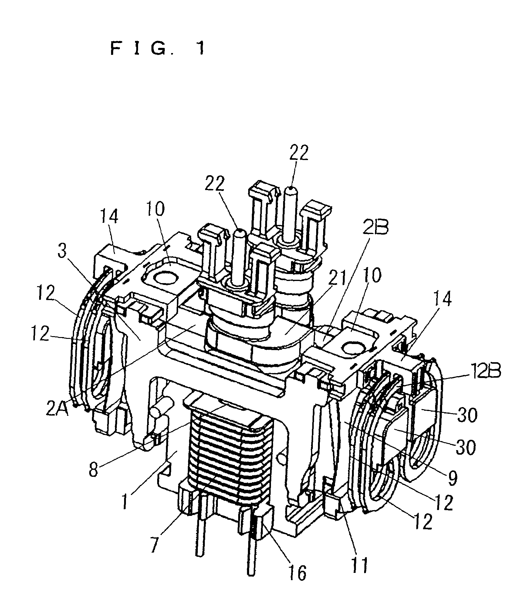
[0046]A first embodiment of the present invention is described with reference to FIGS. 1 to 5. FIG. 1 is a perspective view showing a constitution of an oscillation type linear actuator in accordance with the first embodiment, and FIG. 2 is an exploded perspective view thereof. FIG. 3 is a front view showing a configuration of a coupling member 12, which will be described below. FIG. 4 is aside view showing a constitution of a main section around the coupling member 12, and FIG. 5 is a front view thereof.

[0047]The oscillation type linear actuator is formed for a driving source of a reciprocation type power shaver, and comprises a stator 1, a pair of moving members 2A and 2B, a chassis 3, a pair of suspenders 9 for suspending the moving members 2A and 2B from the chassis 3, four coupling members 12 for coupling two moving members 2A and 2B, and so on.

[0048]The stator 1 is an electromagnet in which a coil 7 is wound around a laminated body of iron plate of magnetic material or a sinte...


PUM


Abstract

In an oscillation type linear actuator for reciprocally moving a plurality of moving members held in parallel with each other in a predetermined direction owing to electromagnetic action between a stator and them, two moving members reciprocally moving in opposite phases with each other are coupled by a coupling member having spring function, and a non-displacing portion of a plate spring portion of the coupling member which is not displaced substantially is restricted by a stopper. Even when an external force is applied to one of two moving members reciprocally moving in the opposite phases each other, motion of the other moving member is transmitted to the moving member via the coupling member, so that reduction of amplitude of the moving member to which the external force is applied can be restricted, and a balance of amplitudes of two moving members is maintained.

Description

TECHNICAL FIELD[0001]The present invention relates to an oscillation type linear actuator used as a driving source of a reciprocation type power shaver, and so on.BACKGROUND ART[0002]Conventionally, oscillation type linear actuators having various constitutions are proposed as a driving source of a reciprocation type power shaver. In a conventional oscillation type linear actuator shown in Publication Gazette of Japanese Patent Application 8-3180610(first conventional art), two moving members are coupled by a coupling member having a spring function and displacing in a direction of reciprocal movement of the moving members, in order to prevent occurrence of uncomfortable vibration without losing a balance of oscillation of the moving members, even when a force is externally applied to one of the moving members oscillated in opposite phases with each other.[0003]When a large load is applied to only one of the moving members while the moving members are respectively driven reciprocall...

Claims


Application Information

Patent Timeline
Patent Type & Authority Patents(United States)
IPC IPC(8): F16K51/00H02K33/16
CPCH02K33/16B26B19/288B26B19/282B26B19/28H02K33/04
Inventor SHIMIZU, HIROAKIYABUUCHI, HIDEKAZUMORIGUCHI, MASASHIKOBAYASHI, NOBORUMOTOHASHI, RYOOTANI, RYUJI
Owner MATSUSHITA ELECTRIC WORKS LTD
Learn More