Working machine lifting device of tractor

a technology of lifting device and working machine, which is applied in the direction of adjusting device, agricultural machinery, agricultural tools and machines, etc., can solve the problems of short strength and rigidity of the single hydraulic cylinder for lifting the working machine, increase the gap between the tractor and the working machine, and undesirable widened gap, so as to facilitate the exhaust of contamination, reduce the stress on the lifting arm, and reduce the effect of parts coun

Inactive Publication Date: 2006-01-31
YANMAR CO LTD
View PDF5 Cites 14 Cited by
  • Summary
  • Abstract
  • Description
  • Claims
  • Application Information

AI Technical Summary

Benefits of technology

[0014]In the working machine lifting device of a tractor, preferably, the externally installed cylinder and the lower link are rotatably supported on a same pin so that the support point of the cylinder and the vertical rotating pivot of the lower link are positioned on the axis of the pin. Therefore, it is unnecessary to provide separate pins for pivoting the hydraulic cylinder and the lower link, thereby saving a parts count. Further, a space required to pivot the externally installed hydraulic cylinder and the lower link can be reduced so as to facilitate saving of spaces.
[0026]Preferably, biasing means is disposed in the attaching portion so as to bias the roller toward the center of the slot, thereby preventing the piston rod and the lift arm from being caught on each other. Another effect is that the movement of the piston rod and the lift arm relative to each other is moderated so as to protect the hydraulic cylinder, the lift arm, the working machine, and so on from a sudden external force.

Problems solved by technology

The above-mentioned working machine lifting device having the single hydraulic cylinder for lifting the working machine is short in strength and rigidity for lifting a wide or heavy working machine.
However, in this arrangement, both ends of each lift cylinder (one is a basal end of its cylinder casing, and the other is a tip of its piston rod) are pivoted on two respective points (one on an intermediate portion of the lift arm, and the other on the rear side surface of the transmission casing) with such a short distance therebetween as to be restrictive in arranging the externally installed lift cylinder having a large capacity or a large stroke.
However, this arrangement increases the gap between the tractor and the working machine.
Such a widened gap is undesirable in view of lengthwise balance of the tractor coupled with a working machine.
9), thereby complicating and increasing its manufacturing processes.
Additionally, the block must be thick so as to have the oil holes bored therein, thereby being heavy and expensive.
Further, in the conventional working machine lifting device, piston rods of the externally installed cylinders are exposed and subject to sticking or hitting of sand or mud causing damage and corrosion of their sliding surfaces.
Thus, a marketable hydraulic cylinder cannot serve as the externally installed hydraulic cylinder requiring to be processed for forming the bracket.
However, depending on the degree the cylinder cover may cover the cylinder, it may happen that earth and sand enters the gap between the cylinder and the cylinder cover.

Method used


Image

  • Working machine lifting device of tractor
  • Working machine lifting device of tractor
  • Working machine lifting device of tractor

Examples


first embodiment

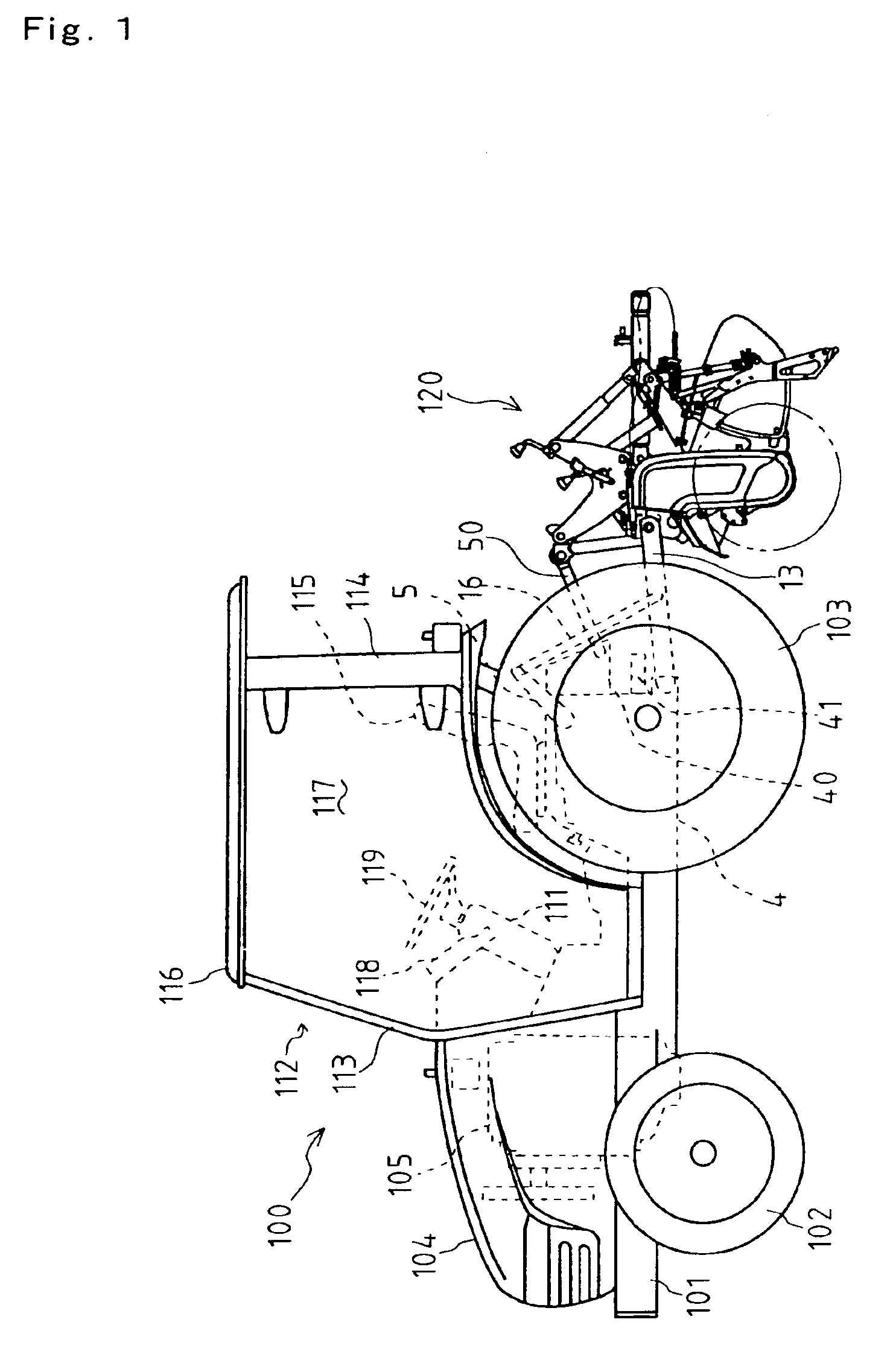
[0048]At first, a tractor 100 equipped with a working machine lifting device 1 serving as the working machine lifting device of the present invention will be described with reference to FIGS. 1 to 4.

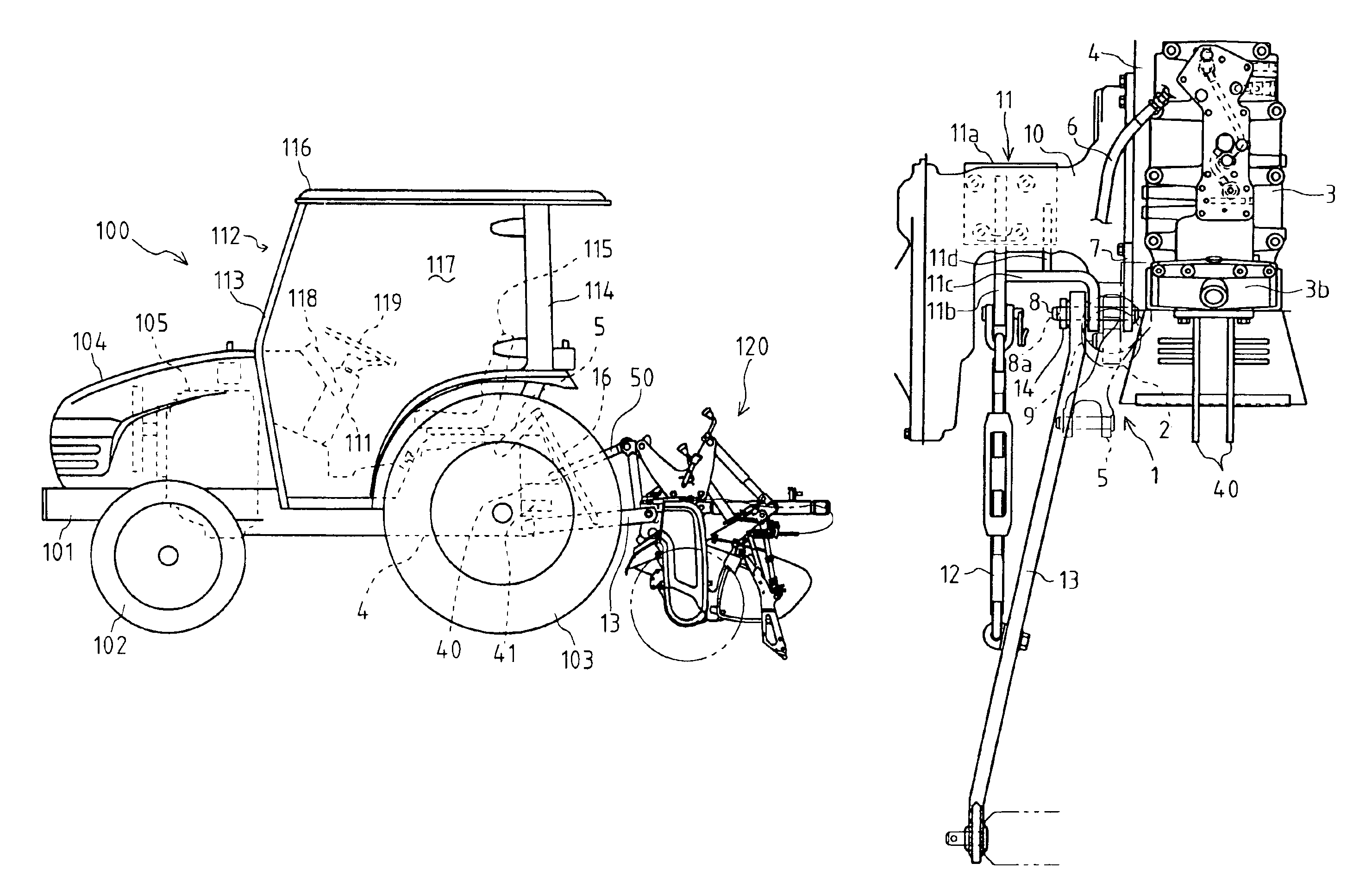
[0049]As show in FIG. 1, tractor 100 has an engine frame 101 supporting a pair of front wheels 102 via a front axle casing. A transmission casing 4 is disposed rearward from engine frame 101 with a clutch housing therebetween. Left and right rear wheels 103 are supported on both lateral sides of transmission casings via respective rear axle casings 10. A working machine 120 can be coupled to the rear portion of transmission casing 4 via a three-point linkage (working machine coupling three-point linkage) comprising a top link 50 and a pair of right and left lower links 13. A front wheel driving output shaft is extended forward from the lower front portion of transmission casing 4 so as to drive right and left front wheels 102 via universal joints, a transmission shaft, and others.

[0050]A...

second embodiment

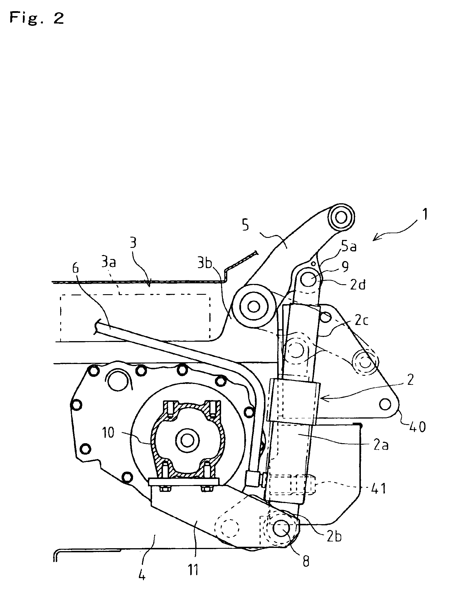
[0055]Since the configure of working machine lifting device 1 is laterally symmetrical, FIGS. 2 to 4 illustrate only the left portion of working machine lifting device 1 in which lift arm 5, lift cylinder 2 and others are disposed, and they do not illustrate the right portion thereof. Hereinafter, each of the right and left portions of working machine lifting device 1 will be described on the assumption that the illustrated left portion of working machine lifting device 1 represents the right portion thereof unless any member in the right portion is mentioned specially. A later-discussed working machine lifting device 15 serving as the working machine lifting device will be described similarly in the state that FIG. 6 and others illustrate only the left portion thereof.

[0056]Lift cylinder 2 comprises a cylinder casing 2a, a pivoted portion 2b on the casing side, a piston rod 2c, and a pivoted portion 2d on the rod side. A hydraulic oil pipe 6 is connected at one end thereof to a sid...

third embodiment

[0078]Next, a tractor equipped with a working machine lifting device 15 according to the present invention will be described with reference to FIGS. 6 to 11.

[0079]Working machine lifting device 15 of the second embodiment has a different mechanism for leveling working machine 120 while having the substantially similar arrangement of connecting lift cylinders 2 to respective lift arms 5 and transmission casing 4, in comparison with working machine lifting device 15 of the first embodiment.

[0080]As shown in FIG. 6, a leveling cylinder 15 is interposed in lift rod 16 between either right or left lift arm 5 and lower link 13. In FIG. 6, leveling cylinder 16 appears being extended from left lift arm 5, however, this appearance is provided for only convenience. Namely, leveling cylinder 17 may be alternatively interposed between right lift arm 5 and right lower link 13. In FIG. 10, hydraulic oil pipes 18a and 18b to leveling cylinder 17 are extended rightward from hydraulic valve unit 3 s...


PUM


Abstract

A working machine lifting device of a tractor, comprising externally installed hydraulic lift cylinders disposed on the right and left sides of a transmission casing, lift arms rotated by the operation of the cylinders, and lower links vertically rotated by the rotation of the lift arms and connected to a working machine, wherein the cylinder and the lower link are rotatably supported on a same pin supported by the transmission casing and a sway chain bracket, and the support point of the cylinder and the vertical rotating pivot of the lower link are positioned on the axis of the pin.

Description

[0001]Continuation of prior PCT application No.: PCT / JP03 / 04375, filed Apr. 4, 2003TECHNICAL FIELD[0002]The invention relates to a working machine lifting device disposed on a tractor body, and particularly relates to that having an externally installed hydraulic cylinder serving as a working machine lifting actuator.BACKGROUND ART[0003]Conventionally, a working vehicle such as a tractor provided at is rear portion with a working machine coupling linkage, usually including a single top link and a pair of left and right lower links, through which a working machine can be attached to the vehicle. The working machine coupling linkage is provided with a working machine lifting device which operates an actuator such as a hydraulic cylinder so as to lift and lower a working machine.[0004]The hydraulic actuator (lift cylinder) is installed in a housing mounted on a transmission casing. A piston rod of the lift cylinder is connected to the right and left lower links via lift arms for liftin...

Claims


Application Information

Patent Timeline
Patent Type & Authority Patents(United States)
IPC IPC(8): A01B59/043A01B59/06
CPCA01B59/068
Inventor OCHI, TOMOFUMIISOGAI, TAKAYUKIHAYASHI, KEIICHI
Owner YANMAR CO LTD
Why Eureka
Try Eureka