
Capacitance type sensor

a capacitance type, sensor technology, applied in the direction of force measurement, resistance/reactance/impedence, instruments, etc., can solve the problems of unsatisfactory reliability of the force sensor, affecting the efficiency of the the failure of the force sensor 510 illustrated in fig. 36, etc., to achieve the effect of improving the efficiency of transmission of external force received by the detective member, reducing manufacturing costs, and improving the efficiency of the detectiv

Inactive Publication Date: 2006-01-24
NITTA CORP
View PDF25 Cites 43 Cited by
  • Summary
  • Abstract
  • Description
  • Claims
  • Application Information

AI Technical Summary

Benefits of technology

[0015]In the above constructions, the conductive member used in common for constituting the first and second capacitance elements is electrically coupled with the reference electrode grounded or kept at a certain potential, not by being in direct contact with the reference electrode but through capacitive coupling. Therefore, the withstand voltage characteristic of the sensor is improved and the sensor is hardly broken due to the flow of a spark current. Besides, a bad condition in electrical connection or the like can be prevented. Thus, a highly reliable capacitance type sensor can be obtained. In addition, since the first and second capacitance elements are connected in series with each other, by providing wiring only on a member such as the substrate supporting the capacitance element electrode and the reference electrode, any wiring for grounding the conductive member or keeping it at a certain potential need not separately be provided. Therefore, a capacitance type sensor having a simple structure can be manufactured through a less number of manufacturing steps.
[0033]Any of the capacitance type sensors of the present invention preferably further comprises a supporting member made of an elastic material for supporting the conductive member. In this construction, since the supporting member is made of an elastic material, the impact of the external force can be relieved and so the damage of the capacitance type sensor can be relieved. Further, the water and dust proofing can effectively be obtained between the supporting member and a cover case. In addition, by an elastic restoring force of the supporting member, the conductive member can automatically be returned to its original position when a force is relieved.

Problems solved by technology

There is a possibility of a trouble with or a breakdown of the force sensor 510.
Besides, if the electrical connection between the electrodes 540 and 500 has become bad due to aged deterioration or the like, an accurate sensor output cannot be obtained.
Thus, the force sensor 510 illustrated in FIG. 36 is unsatisfactory in view of its reliability.
However, providing both of the fixed and flexible substrates 620 and 621 with such wires brings about a complicated structure and a complicated manufacturing process of this kind of acceleration sensor.

Method used


Image

  • Capacitance type sensor
  • Capacitance type sensor
  • Capacitance type sensor

Examples


first embodiment

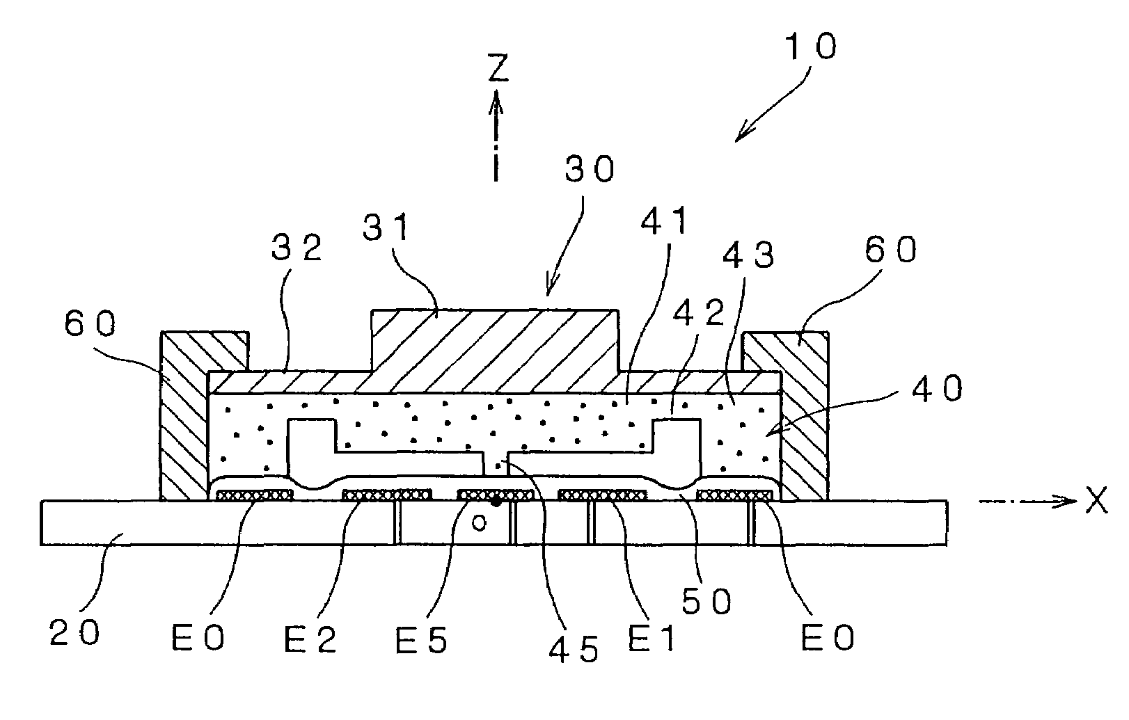
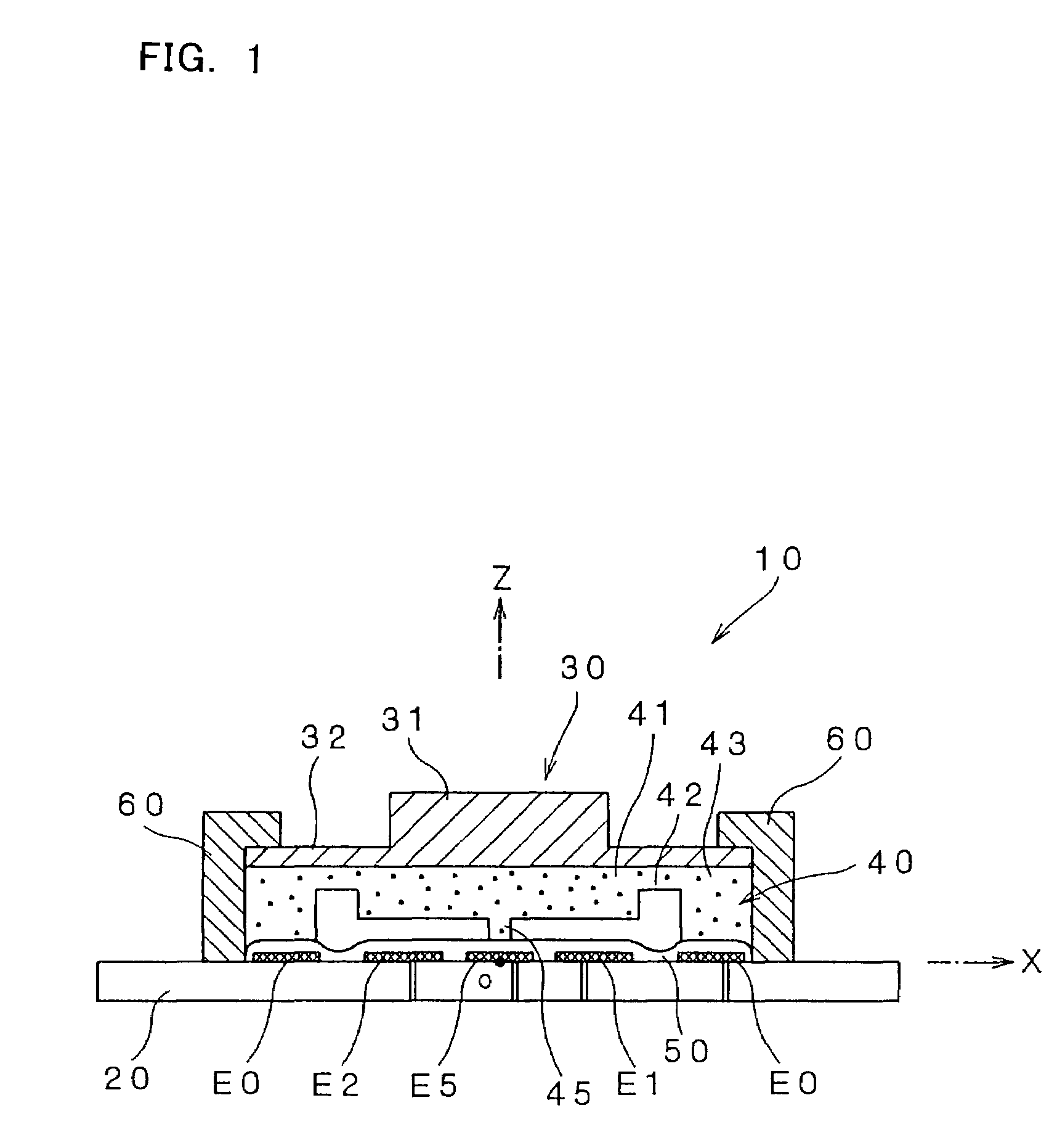
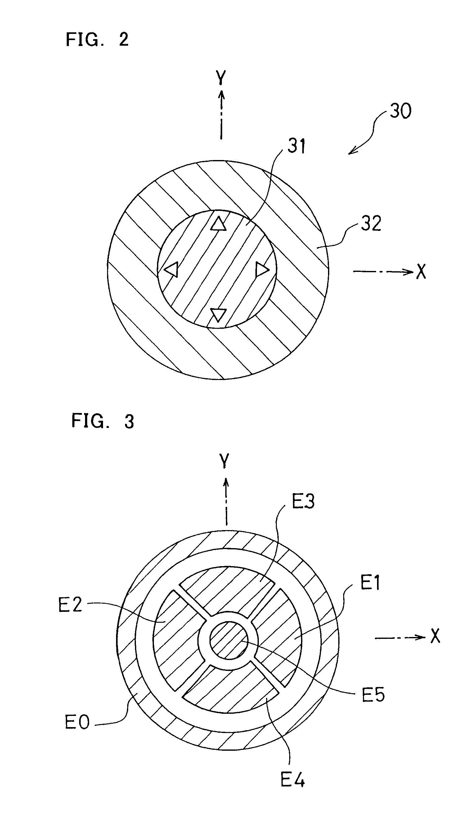
[0075]FIG. 1 is a schematic sectional view of a capacitance type sensor according to the present invention. FIG. 2 is an upper view of a detective member of the capacitance type sensor of FIG. 1. FIG. 3 illustrates an arrangement of electrodes formed on a substrate of the capacitance type sensor of FIG. 1.

[0076]The capacitance type sensor 10 includes a substrate 20, a detective member 30 as an operation member to which a force is externally applied by being operated by a person or the like, a displacement electrode 40, capacitance element electrodes E1 to E5 and a reference electrode (a common electrode) E0 formed on the substrate 20, an insulating film 50 formed in close contact with the capacitance element electrodes E1 to E5 and the reference electrode E0 to cover the corresponding part of the upper portion of the substrate 20, and a supporting member 60 for supporting and fixing the detective member 30 and the displacement electrode 40 to the substrate 20.

[0077]For convenience o...

second embodiment

[0160]Next, the present invention will be described with reference to drawings.

[0161]FIG. 19 is a schematic sectional side view of a capacitance type sensor according to the second embodiment of the present invention. FIG. 20 is an upper view of detective buttons of the capacitance type sensor of FIG. 19. FIG. 21 illustrates an arrangement of electrodes formed on a substrate of the capacitance type sensor of FIG. 19.

[0162]The capacitance type sensor 110 includes a substrate 120, detective buttons 130, displacement electrodes 140, capacitance element electrodes E101 to E105 and reference electrodes E100a and E100b formed on the substrate 120, an insulating film 150 formed in close contact with the capacitance element electrodes E101 to E105 and the reference electrodes E100a and E100b to cover the upper portion of the substrate 120, a supporting member 160 for supporting and fixing the detective buttons 130 and the displacement electrodes 140 to the substrate 120, and a cover case 17...

third embodiment

[0187]Next, the present invention will be described with reference to drawings.

[0188]FIG. 24 is a schematic sectional side view of a capacitance type sensor according to another embodiment of the present invention. FIG. 25 is an upper view of detective buttons of the capacitance type sensor of FIG. 24. FIG. 26 illustrates an arrangement of electrodes formed on the substrate of the capacitance type sensor of FIG. 24.

[0189]The capacitance type sensor 210 includes a substrate 220, detective buttons 230, a displacement electrode 240, capacitance element electrodes E201 to E204 formed on the substrate 220, a fixed switch electrode E205, a movable switch electrode E208, a reference electrode E200, an insulating film 250 formed in close contact with the capacitance element electrodes E201 to E204 to cover the upper portion of the substrate 220, an insulating film 251 formed in close contact with the movable switch electrode E208 to cover the upper portion of the insulating film 250, a supp...


PUM

PropertyMeasurementUnit
capacitanceaaaaaaaaaa
distanceaaaaaaaaaa
time constantaaaaaaaaaa

Abstract

Capacitance element electrodes (E1 to E5) and a grounded reference electrode (E0) are formed on a substrate (20). At a position opposite to these electrodes (E0 to E5), a displacement electrode (40) is disposed that is Z-axially deformable as a detective member (30) is externally operated to move Z-axially. The displacement electrode (40) cooperates with the reference electrode (E0) and capacitance element electrodes (E1 to E5) to form capacitance elements (C0 to C5), respectively. Each of the capacitance elements (C1 to C5) is connected in series with the capacitance element (C0) with respect to a signal externally input. Changes in the capacitance values of the capacitance elements (C1 to C5) as the detective member (30) is moved are detected to sense the displacement of the detective member (30).

Description

TECHNICAL FIELD[0001]The present invention relates to capacitance type sensors suitably used for inputting operations in multidimensional directions, particularly to capacitance type sensors good in withstand voltage characteristic and capable of simplifying the manufacturing process.BACKGROUND ART[0002]A capacitance type sensor is used as a device for converting, into an electric signal, the intensity and direction of a force applied by an operator. For example, as an input device for a game machine used is a device incorporated as a capacitance type force sensor (so-called joy stick) for inputting operations in multidimensional directions.[0003]Using the capacitance type sensor, an operation quantity with a predetermined dynamic range can be input as the intensity of a force applied by the operator. Such a sensor may be used in the form of a two-dimensional or three-dimensional force sensor capable of detecting each directional component divided from the applied force. In particul...

Claims


Application Information

Patent Timeline
Patent Type & Authority Patents(United States)
IPC IPC(8): G01R27/26G01L1/00
CPCG06F3/0338G01B7/00
Inventor MORIMOTO, HIDEO
Owner NITTA CORP
Learn More