
Calendar slide

Inactive Publication Date: 2006-01-24
STUEBING AUTOMATIC MACHINE
View PDF18 Cites 6 Cited by
  • Summary
  • Abstract
  • Description
  • Claims
  • Application Information

AI Technical Summary

Benefits of technology

[0010]It is, therefore, an objective of the present invention to provide an improved slide that will not have a tendency to stick together when nested.
[0011]It is further an objective of the present invention to provide an improved slide that will maximize the capacity of the magazine of a binding or tinning machine.
[0012]It is another objective of the present invention to provide an improved slide which will have a reduced tendency toward scratching or marring when the slides are stacked or nested together or used in a tinning machine.
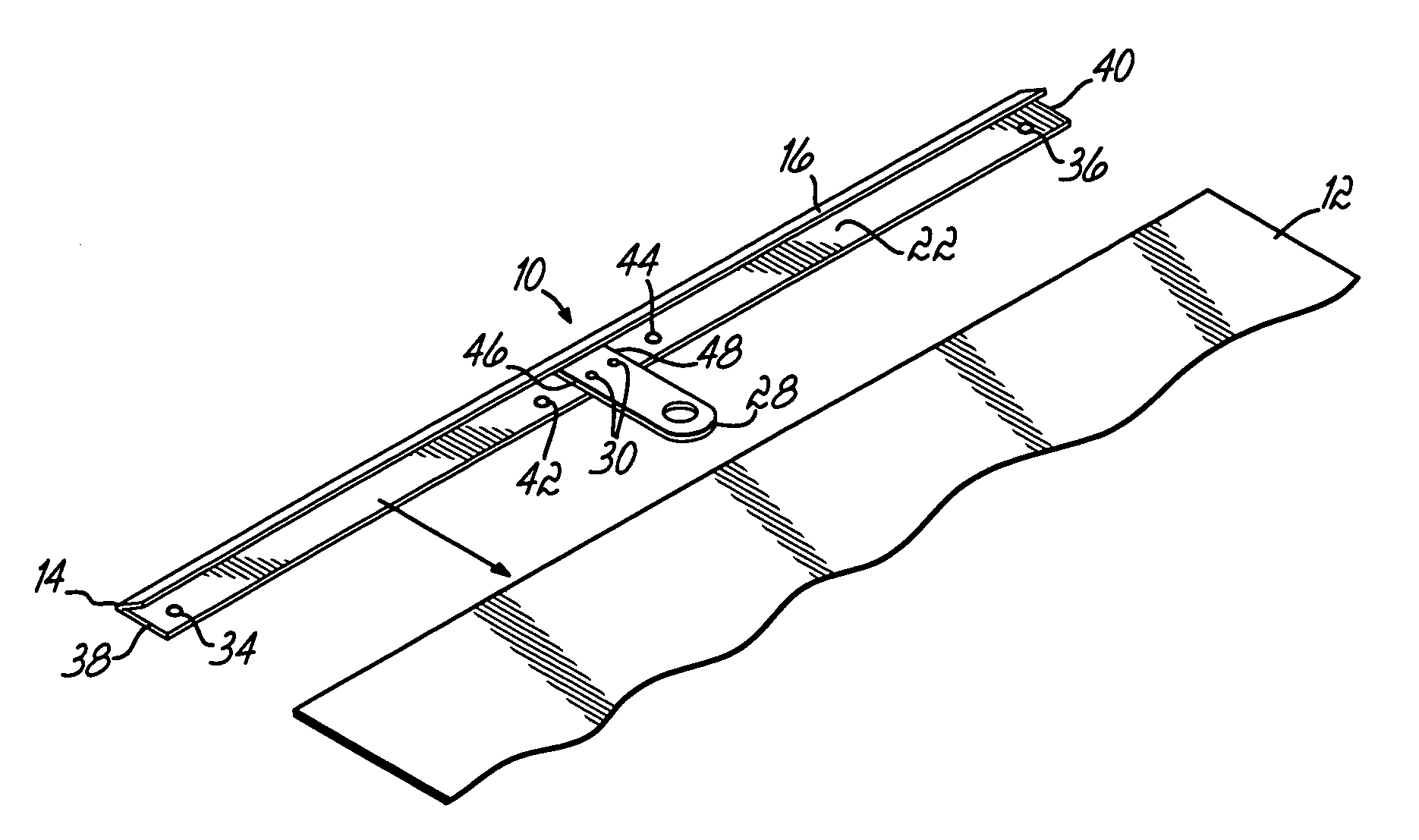
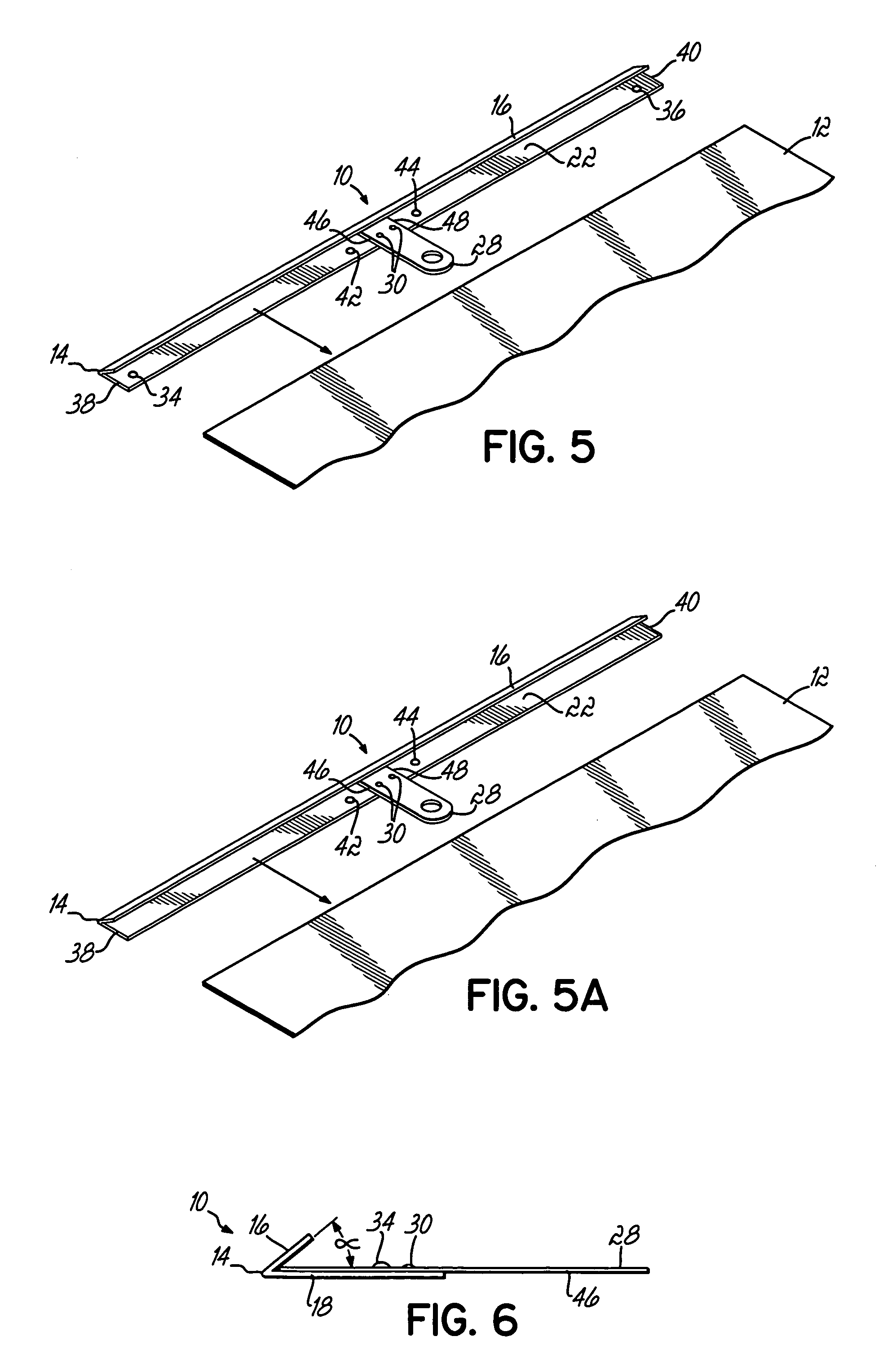
[0013]These and other objectives of the present invention are achieved with an improved slide. More specifically, in some embodiments of this invention, convex bulges are placed near the longitudinal ends of the slide and / or near the longitudinal center of the slide. These convex bulges provide an air gap between adjacent slides, thus lessening the likelihood of multiple nested slides sticking together. The multiple convex bulges also serve to promote a uniform stacking of slides in a tinning machine's magazine or when stored or shipped. Finally, the convex bulges also provide a buffer between the protruding rivets or burrs of a hanger and the slides' painted or coated exterior, thus minimizing the possibility of scratches due to contact with adjacent slides.

Problems solved by technology

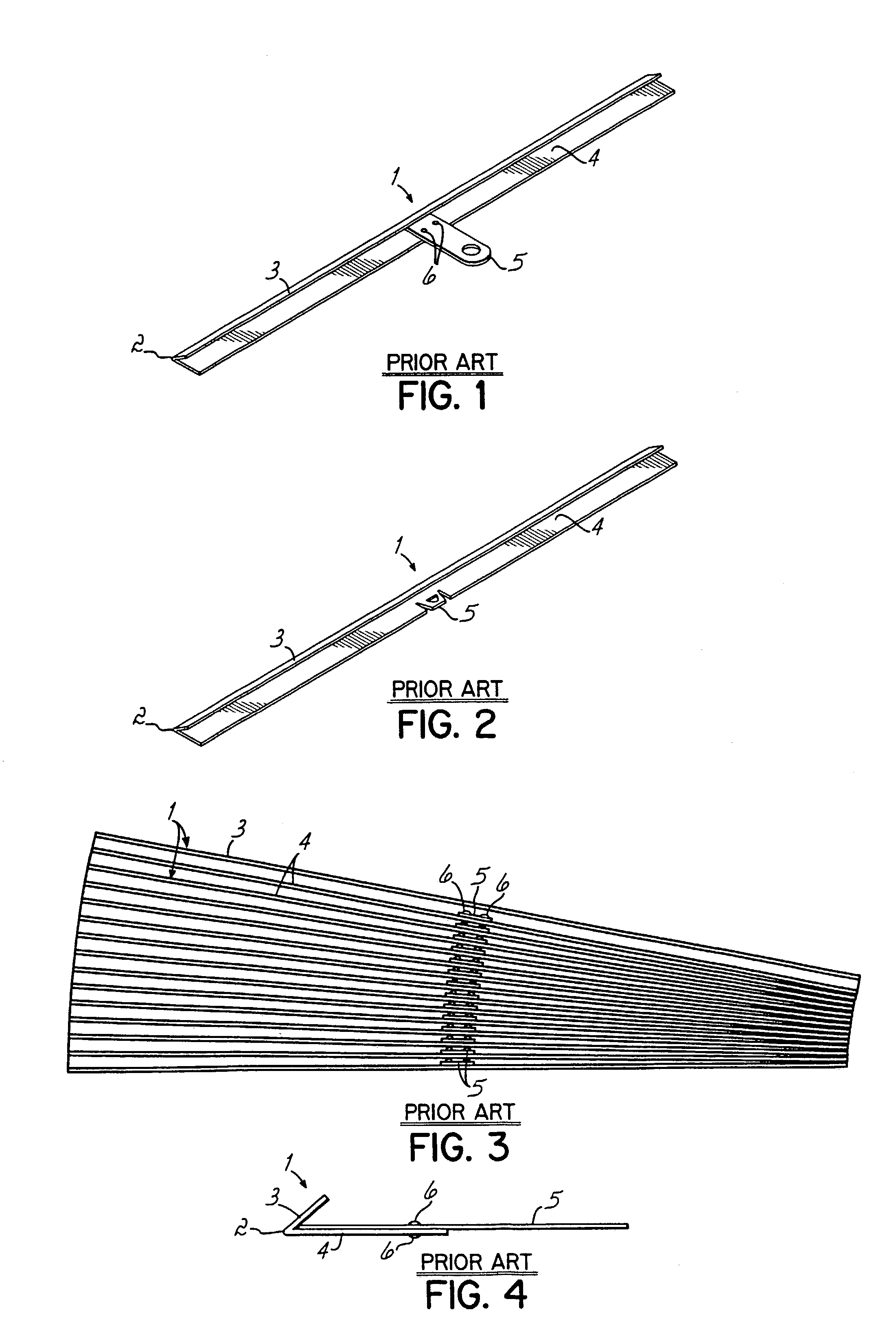
There are a number of problems with these prior art slides.
First, the slides have a tendency to stick together when they are stacked or nested tightly together.
This is particularly problematic when a binding or tinning machine is being used to install a slide on a calendar.
Accordingly, while stuck-together slides could be an annoyance, and could take extra time to separate, an operator could at least see the problem and separate the slides.
Accordingly, now when slides stick together, they not only become more difficult to feed from the magazine or hopper, but there is also an increased tendency for multiple stuck-together slides to be fed into the tinning station, causing the machine to jam or malfunction.
Another problem with the traditional slide is that, as shown in FIG. 3, when the slides are stacked or nested together, the attached hanger 5 and the associated rivets or burrs 6 tend to act as a fulcrum and, as the stack grows, cause one end of the slides to fan or bow out.
This lack of stackable uniformity can increase the space required for shipping or storing the slides.
Decreasing the capacity of the tinning machine's magazine means that it must be more frequently refilled, thus decreasing the overall efficiency and productivity of the binding operation.
Additionally, when the slides shown in FIGS. 1 and 4 are stacked or nested together in a tinning machine magazine or in the case of shipment or storage, the protruding indentations, bulges, burrs or rivets 6, which often have rough edges, can scratch the painted exterior of an adjacent slide, causing unsightly marks and contributing to either a less than desirable end product, or a product that must be discarded due to quality control standards.
Thus, this has the undesirable effect of creating a nonuniform stack of slides which results in a decreased tinning machine magazine capacity, increased difficulty in feeding the slides from a magazine, and increased likelihood of feeding malfunctions.
Moreover, when the longitudinal center sags, bends, or bows, there is an increased tendency for the burrs or rivets to contact and scratch or mar the painted or coated exterior of the second wider bend portion.
Moreover, when a slide with concave indentations is used in a binding or tinning machine, the crimping bars of the binding machine move directly against the painted and protruding surface of the concave indentations and tend to scratch or remove the paint from such protrusions.

Method used


Image

  • Calendar slide
  • Calendar slide
  • Calendar slide

Examples


Embodiment Construction

[0029]Presently preferred embodiments of the present inventive slide 10 are seen in FIGS. 5 through 11. It will be understood by those in the art that, while the present invention may be described as a calendar slide 10, the slide 10 may be used to bind and hang or display any other desired display item, such as a poster, document, banner, wall hanging, or workpiece 12.

[0030]The calendar slide 10 is typically made from a strip of sheet metal, although other substances with similar characteristics could be used. The typical sheet metal used is a cold rolled mild steel plate with a thickness of approximately 0.0062 inches; however, other types and / or sizes of metal could also be used. The sheet metal is bent to form longitudinal bend 14, which creates a generally V-shaped channel from the sheet metal strip. The longitudinal bend 14 in the sheet metal channel separates a first bend portion or leg 16 and a wider second bend portion or leg 18. According to one embodiment, the width of th...


PUM


Abstract

A calendar slide for binding a margin of a calendar or a poster and allowing the same to be hung by a hanger in a desired location, such as a wall. Spaced convex bulges in the calendar slide prevent the slides from sticking together during the storage, shipment, and binding processes, and also promote uniform stacking of the slides in a tinning machine magazine, and finally prevent the adjacent nested slides from scratching or marring one another.

Description

[0001]This is a continuation-in-part of U.S. patent application Ser. No. 10 / 321,413 filed Dec. 17, 2002 now abandoned and hereby incorporated by reference in its entirety.FIELD OF THE INVENTION[0002]This invention relates to document binders. More specifically, this invention relates to the art of binding calendars, posters, documents, and banners with a binding strip and a method for making the same.BACKGROUND OF THE INVENTION[0003]Slides for binding a margin of a calendar, poster, document, banner, or other wall hanging are known in the art. Examples of prior art slides are shown in FIGS. 1–4, and such a slide 1 is generally an elongated strip of roughly V-shaped sheet metal. The vertex 2 of the elongated V-shaped strip of sheet metal separates the two sides or legs 3,4 of the V-shaped strip. Typically, one side or leg 3 of the V-shaped strip is shorter or narrower, and the other side or leg 4 is longer or wider. The slide 1 also typically contains a hanger 5 which, as shown in FI...

Claims


Application Information

Patent Timeline
IPC IPC(8): G09D3/00B42F1/02B42DB42D5/04B42FB42F1/04G09F17/00
CPCB42B5/06B42P2241/10
Inventor GAVRONSKY, ALLAN
Owner STUEBING AUTOMATIC MACHINE
Learn More