
Endovascular prostethic devices having hook and loop structures

a prostethic device and endovascular technology, applied in the field of multi-component endovascular prostheses, can solve the problems of increasing the risk of perioperative or post-operative complications, and patients not ideal candidates for triple-a procedures. , to achieve the effect of minimally invasive and effectiv

Inactive Publication Date: 2006-01-17
SCI MED LIFE SYST +1
View PDF24 Cites 61 Cited by
  • Summary
  • Abstract
  • Description
  • Claims
  • Application Information

AI Technical Summary

Benefits of technology

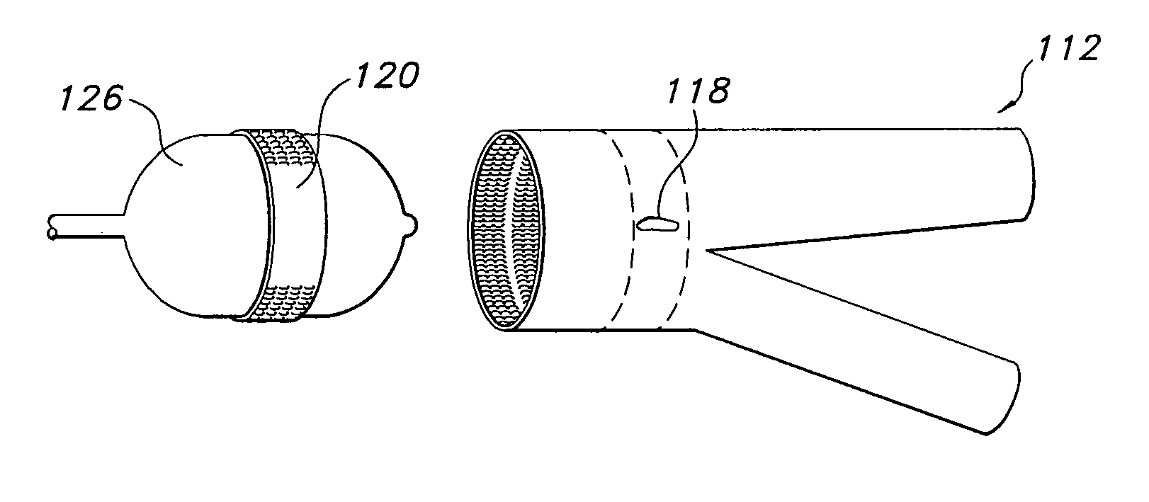
[0012]Additionally, the present invention is directed to an endovascular prosthesis and method of repairing the same, wherein the prosthesis includes a patch for the repair of a worn section of an endovascular member. The member and patch have hook and loop structures cooperative with one another such that the patch may be introduced endovascularly and applied to the stent-graft in situ, thereby forming a fluid-tight seal over the worn area. Endovascular introduction of the patch permits repair of the damaged endovascular member in an effective and minimally-invasive manner.
[0015]In another aspect, the present invention is directed to a multi-component endovascular prosthesis which includes: (1) a first prosthetic component which has a structure comprising one of a hook structure and a loop structure; and (2) a second prosthetic component which has a structure comprising the other of the hook structure and the loop structure. The hook structure and the loop structures are matingly engageable so as to maintain the first prosthetic component in substantially fluid tight engagement with the second prosthetic component.
[0017]In a further method aspect, the present invention is directed to a method for the assembly of an endovascular prosthesis which is implantable within a body lumen, which includes the steps of: (1) providing a first prosthetic component having one of a hook or loop structure; (2) providing a second prosthetic component having the other of the hook or loop structure; and (3) engaging in situ the hook structure or the loop structure of the first prosthetic component with the other of the hook structure or the loop structure of the second prosthetic component so as to maintain the first prosthetic component in substantially fluid tight engagement with the second prosthetic component. The endovascular prosthesis is useful for the treatment of aneurysms, particularly abdominal aortic aneurysms.

Problems solved by technology

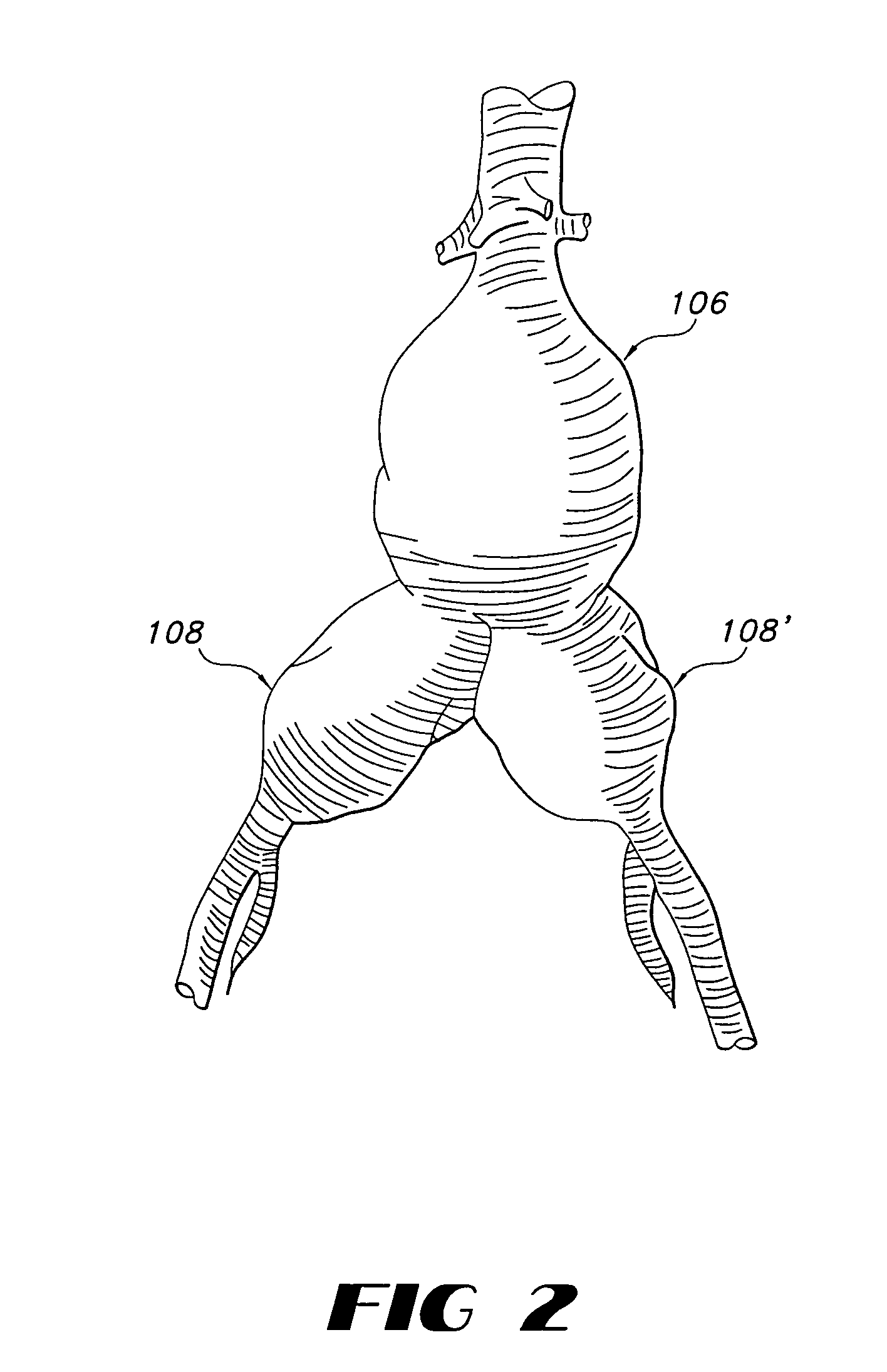
The aneurysm may rupture if it is not detected and treated, causing massive hemorrhaging which is likely to be fatal to the patient.
Many patients experiencing such AAAs, however, are over 65 years of age and often have other chronic illnesses which increase the risk of perioperative or post-operative complications.
Thus, such patients are not ideal candidates for triple-A procedures.
Further, this procedure is generally not performed successfully once an aneurysm has ruptured due to the extensiveness of the surgery and the time required to prepare a patient for surgery.
The in situ positioning of stent-grafts in this area is more difficult than the positioning of such devices in the lumen of non-bifurcated vessels.
Bifurcated stent-grafts are frequently too bulky to advance through a single iliac artery, particularly in view of the fact that the limb for the contralateral branch of the stent-graft must be inserted together with the limb of the ipsilateral branch.
The caudal portion of the graft must not stretch across the mouth of the internal iliac artery which would result in inadvertent occlusion of that artery.
Additional factors such as the severe tortuosity of the iliac arteries and the marked angulation of the aortoiliac junction resulting form the tendency of the abdominal aortic artery to extend caudally during aneurysm formation combine to make deployment of endoluminal bifurcated grafts time consuming and at increased risk of procedural complications and failure.
Additionally, prosthetic devices used in the repair of AAAs have been found to be extremely vulnerable to wearing, particularly as a result of the tortuous nature of vessel lumens.

Method used


Image

  • Endovascular prostethic devices having hook and loop structures
  • Endovascular prostethic devices having hook and loop structures
  • Endovascular prostethic devices having hook and loop structures

Examples


example

In Situ Stent-Graft Deployment

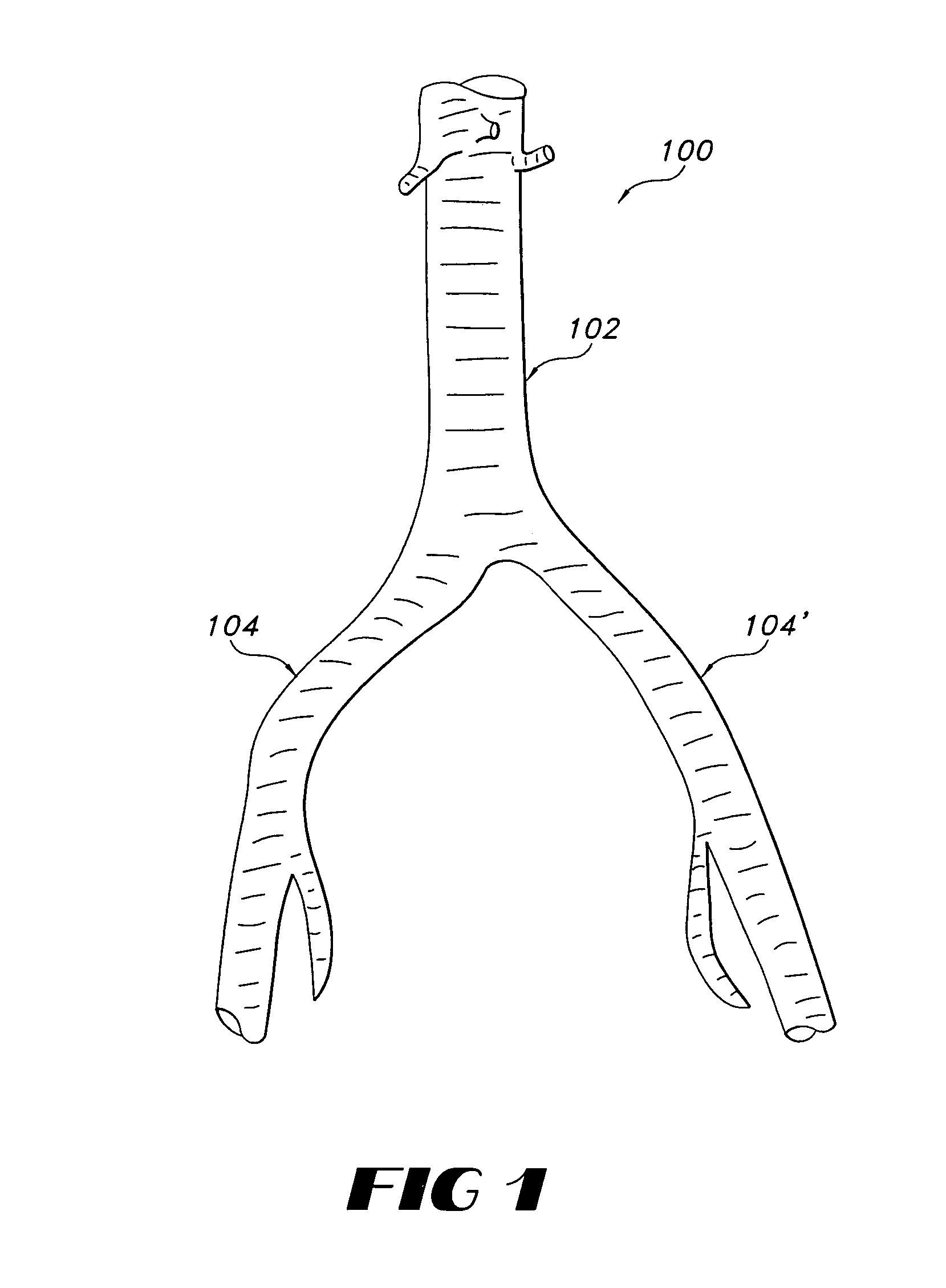
[0046]For purposes of the present example, the term “proximal” refers to a position nearest the heart and the term “distal” refers to a position furthest from the heart. As shown in FIG. 1, the abdominal aorta 102 extends caudally to the common iliac arteries 104 and 104′, which branch to the right and left, respectively. Each common iliac artery branches to an external iliac artery (not shown) which becomes the femoral artery (not shown) below the inguinal ligament (not shown).

[0047]Incisions (not shown) are made which expose the common femoral arteries on the right and left sides. A conventional angiographic guidewire (not shown) is inserted into the incised left femoral artery. The guidewire is advanced until its distal end is above the aneurysm within the vasculature. Typically, the guidewire is at least 0.025 inches in diameter and is composed of tempered stainless steel which is covered with a synthetic material, such as TEFLON®. The guidewire typ...


PUM


Abstract

The prostheses include an endovascular member in need of repair and a patch therefore, as well as prostheses including two or more endovascular members, such as stent-grafts, which may be assembled in situ. Components of the prostheses are held together in substantially fluid tight engagement as the result of hook and loop structures which are present on the members. The hooks engage the loops to secure the components to one another. As a result, the present invention is particularly useful for the in situ repair of damaged prostheses and for the in situ assembly of bifurcated endovascular prostheses, particularly for the treatment of abdominal aortic aneurysms.

Description

FIELD OF THE INVENTION[0001]The present invention is directed to multiple-component endovascular prostheses having textile structures of mating hooks and loops, which maintain the components of the prostheses in substantially fluid tight engagement with one another. More particularly, the present invention is directed to bifurcated endovascular prostheses comprised of two or more stent-graft components having textile structures of hooks and loops which may be assembled in situ for use in bifurcated blood vessels, such as the infrarenal portion of the mammalian aortic artery where it bifurcates to the common iliac arteries.BACKGROUND OF THE INVENTION[0002]An abdominal aortic aneurysm (“AAA”) is an abnormal dilation of the arterial wall of the aorta in the region of the aorta that passes through the abdominal cavity. The condition most commonly results from atherosclerotic disease. Abdominal aortic aneurysms are typically dissecting aneurysms, which are aneurysms that are formed when ...

Claims


Application Information

Patent Timeline
Patent Type & Authority Patents(United States)
IPC IPC(8): A61F2/06A61B17/12A61F2/00
CPCA61F2/07A61F2/0063A61F2002/067A61F2220/0033A61F2220/0083A61F2002/075A61F2002/30467
Inventor SMITH, JOHN K.
Owner SCI MED LIFE SYST
Learn More