
Bariatric device and method

a technology of a bariatric device and a cuff, which is applied in the field of bariatric devices and methods, can solve the problems of large and increasing obesity, and the problem is even greater, and achieve the effect of minimally invasive and effective methods

Active Publication Date: 2010-02-04
BFKW
View PDF17 Cites 120 Cited by
  • Summary
  • Abstract
  • Description
  • Claims
  • Application Information

AI Technical Summary

Benefits of technology

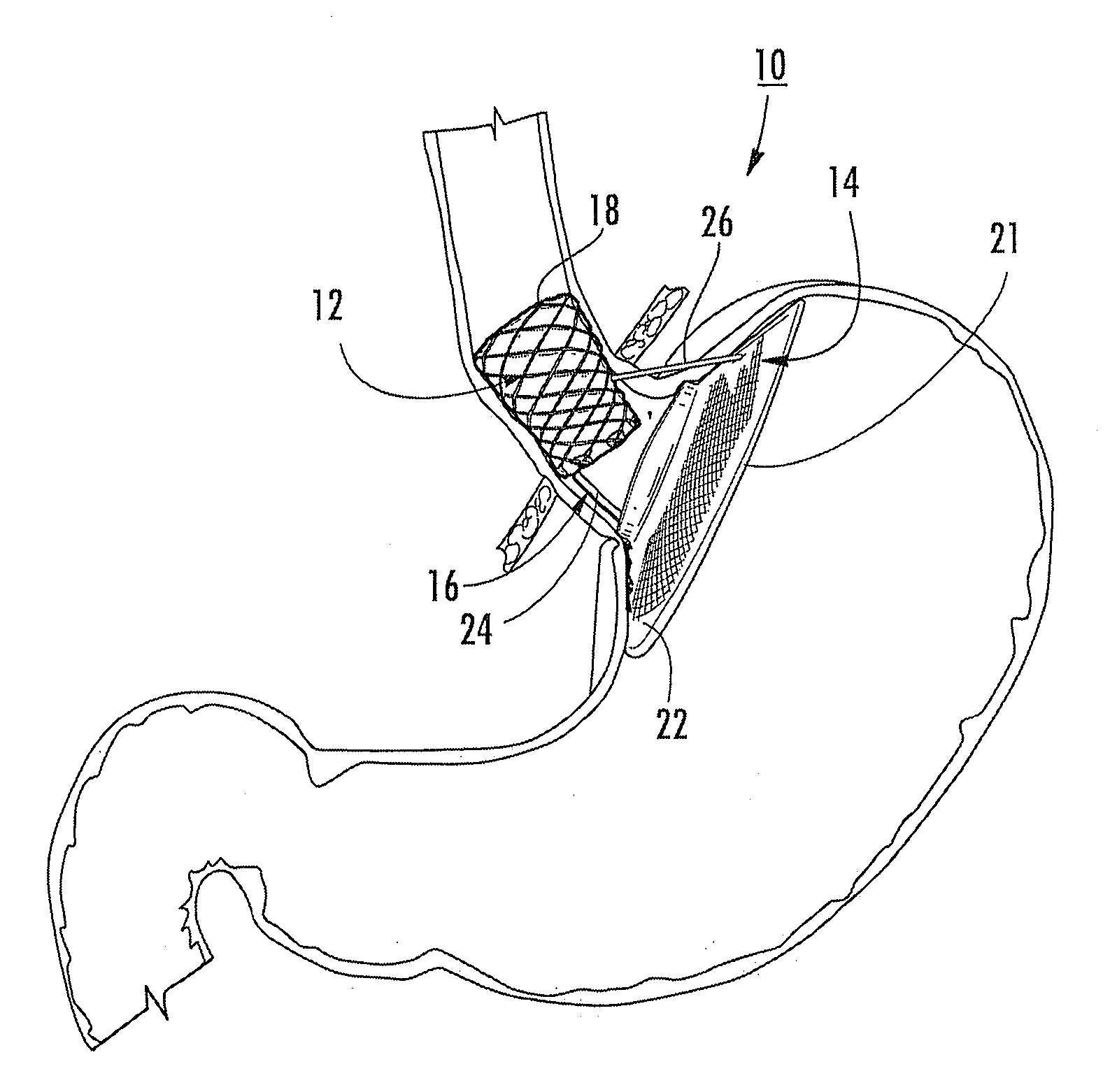
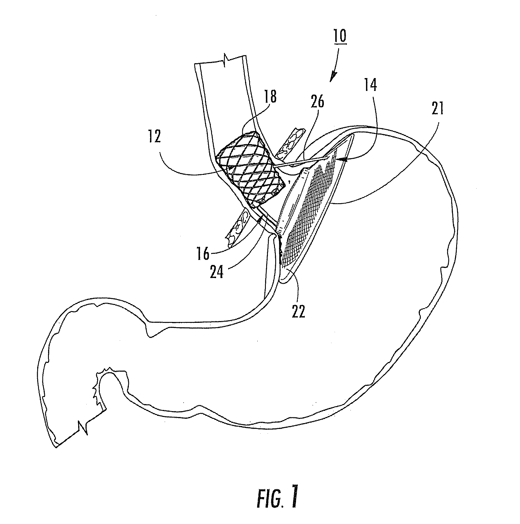
[0004]The present invention provides a bariatric device and method of causing weight loss in a recipient that fulfills this pressing and unmet need in an effective and minimally invasive manner. A bariatric device and method of causing weight loss in a recipient according to an aspect of the invention includes providing an esophageal member, a cardiac member and a connector connected with the esophageal member and the cardiac member. The esophageal member has an esophageal surface that is configured to generally conform to the shape and size of a portion of the esophagus. The cardiac member has a cardiac surface that is configured to generally conform to the shape and size of a portion of the cardiac portion of the stomach.
[0014]The connector may include an adjustable tether. The adjustable tether may include a filament and a tube surrounding the filament to facilitate lengthwise movement of the filament.
[0023]The anchor may include a surface that facilitates tissue attachment and / or tissue ingrowth.

Problems solved by technology

Obesity is a large and increasing problem in the United States and worldwide.
The increasing prevalence of excess body mass among children and adolescents will make the problem even greater when they reach adulthood.

Method used


Image

  • Bariatric device and method
  • Bariatric device and method
  • Bariatric device and method

Examples


Embodiment Construction

[0101]Referring now specifically to the drawings, and the illustrative embodiments depicted therein, a bariatric device, such as an endoluminal bariatric device 10 includes an esophageal member 12, a cardiac member 14, and a connector 16 that is connected with esophageal member 12 and cardiac member 14 (FIGS. 1-14). Esophageal member 12 has a wall 18 defining an esophageal surface 20 that is configured to generally conform to the shape and size of a portion of the esophagus, namely, at the abdominal portion of the esophagus adjacent the gastroesophageal (GE) junction. While illustrated as cylindrical in shape, wall 18 may be other shapes, such as a portion of a cylinder, or the like. Cardiac member 14 includes a body 21 defining a cardiac surface 22 that is configured to generally conform to the shape and size of at least a portion of the cardiac portion of the stomach. Connector 16, which is illustrated as a system of connector members, joins the esophageal and cardiac members. Con...


PUM


Abstract

A bariatric device and method of causing weight loss in a recipient includes providing a bariatric device having an esophageal member, a cardiac member and a connector connected with the esophageal member and the cardiac member. The esophageal member has an esophageal surface that is configured to generally conform to the shape and size of a portion of the esophagus. The cardiac member has a cardiac surface that is configured to generally conform to the shape and size of a portion of the cardiac portion of the stomach. The esophageal surface is positioned at the esophagus. The cardiac surface is positioned at the cardiac portion of the stomach. The bariatric device stimulates receptors in order to influence a neurohormonal mechanism in the recipient.

Description

CROSS REFERENCE TO RELATED APPLICATIONS[0001]This application in a continuation-in-part application which claims priority from U.S. provisional patent application Ser. No. 61 / 107,511, filed on Oct. 22, 2008, U.S. provisional patent application Ser. No. 61 / 159,143, filed on Mar. 11, 2009; and International Patent Cooperation Treaty Application No. PCT / US08 / 53912, filed on Feb. 14, 2008, which claims priority from U.S. provisional patent application Ser. No. 60 / 901,457, filed on Feb. 14, 2007; U.S. provisional patent application Ser. No. 60 / 921,930, filed on Apr. 5, 2007; and U.S. provisional patent application Ser. No. 60 / 931,109, filed on May 21, 2007, the disclosures of which are hereby incorporated herein by reference in their entireties.BACKGROUND OF THE INVENTION[0002]The present invention is directed to a bariatric device and method of causing weight loss in a recipient.[0003]Obesity is a large and increasing problem in the United States and worldwide. In round numbers, from th...

Claims


Application Information

Patent Timeline
Patent Type & Authority Applications(United States)
IPC IPC(8): A61F2/04
CPCA61B17/00234A61F5/0079A61B17/0469A61B17/064A61B17/0643A61B2017/00818A61B2017/0404A61B2017/0464A61B2017/0647A61B2017/0649A61F2/04A61F5/0076A61F5/0083A61F2002/045A61B17/0401
Inventor BAKER, RANDAL S.FOOTE, JAMES A.KEMMETER, PAUL R.WALBURN, FREDERICK J.WILSON, PETER M.LEHMAN, ADAM I.SMITH, BARRY J.CHAPPOLINI, ROBERT J.
Owner BFKW
Learn More