Retarding control for an electric drive machine

a technology of electric drive machine and control panel, which is applied in the direction of propulsion by capacitor, machine/engine, brake system, etc., can solve the problem of discharging undesired power

Active Publication Date: 2006-01-17
CATERPILLAR INC
View PDF21 Cites 53 Cited by
  • Summary
  • Abstract
  • Description
  • Claims
  • Application Information

AI Technical Summary

Problems solved by technology

Additionally, the method includes dissipating undesired power by an application of at least one brake of the propelled machine.

Method used


Image

  • Retarding control for an electric drive machine
  • Retarding control for an electric drive machine
  • Retarding control for an electric drive machine

Examples


Embodiment Construction

[0016]Reference will now be made in detail to the drawings. Whenever possible, the same reference numbers will be used throughout the drawings to refer to the same or like parts.

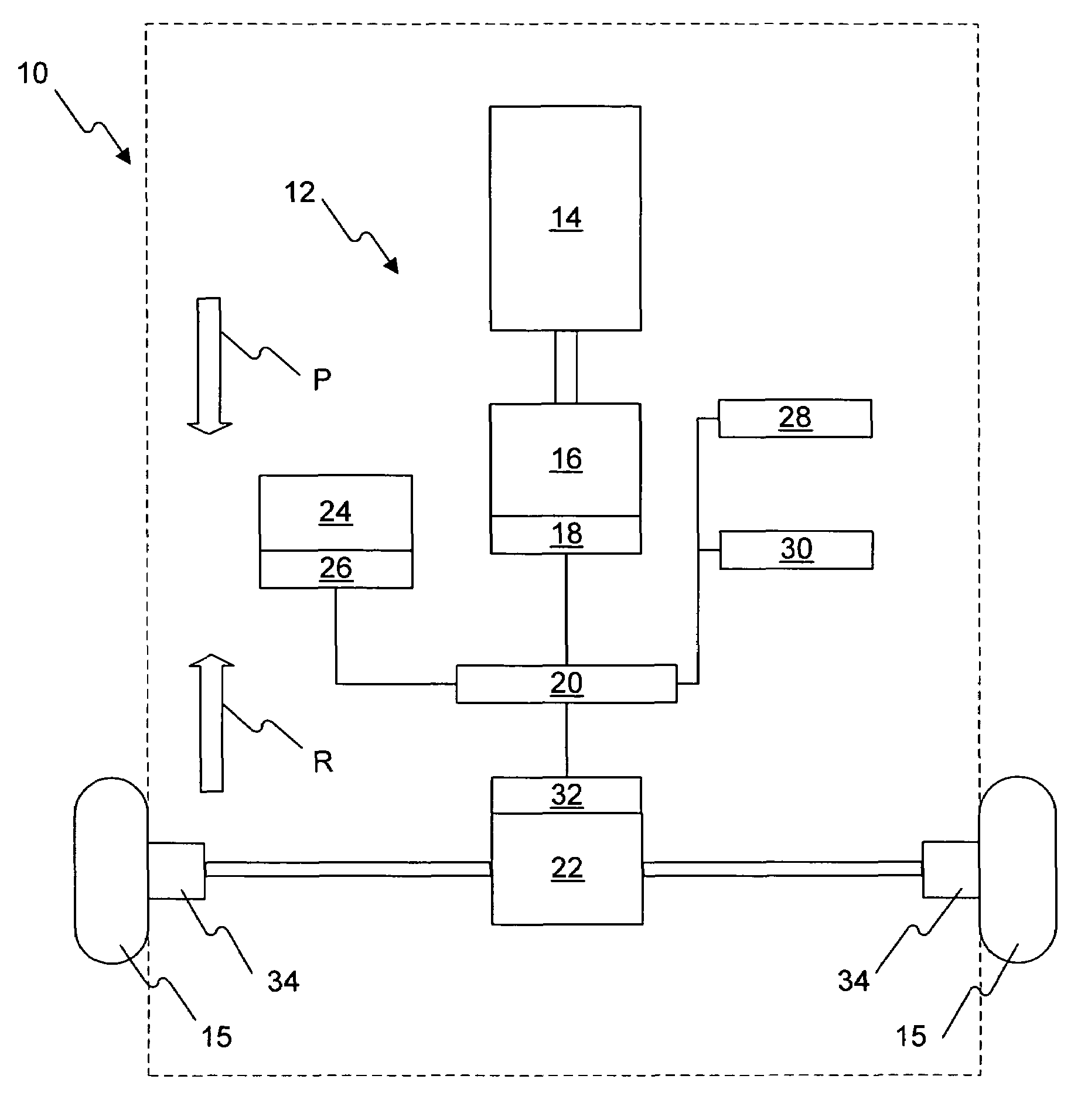
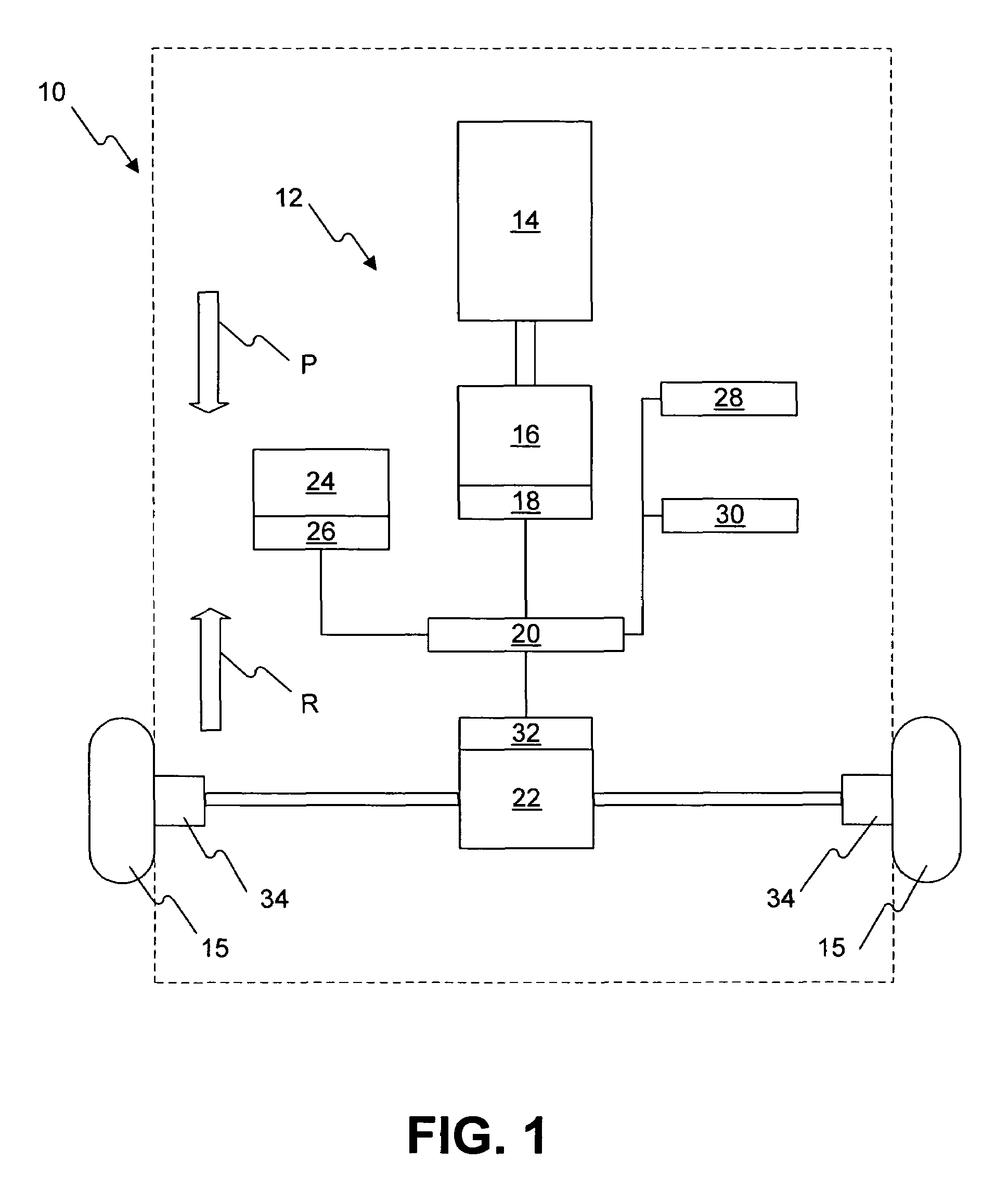
[0017]FIG. 1 schematically illustrates a propelled machine 10 having an electric drive 12 in accordance with an exemplary embodiment of the present disclosure. The electric drive 12 may be used in any type of machine having wheels or sprockets 15 for propelling the propelled machine 10. For example, the electric drive 12 may be used on a dozer machine having tracks propelled by sprockets 15 coupled to the electric drive 12.

[0018]As illustrated in FIG. 1, the electric drive 12 may include an internal combustion engine 14 coupled to provide power to an electric generator 16. The generator 16 may be include power electronics 18 and supply generated current to a direct current bus 20 and one or more electric motors 22. Additionally, the DC bus 20 may be coupled to a resistive grid 24 having associated power elec...


PUM


Abstract

A method of dissipating power in a propelled machine having an electric drive includes converting undesired power to electric power by the electric drive, and driving an internal combustion engine with at least a portion of the electric power prior to substantially dissipating power with any other power dissipating device.

Description

TECHNICAL FIELD[0001]This invention relates to electric drive systems for propelled machines, and more particularly to retarding control for propelled machines having an electric drive.BACKGROUND[0002]Conventional propelled machines may generally include an internal combustion engine that is mechanically coupled through a transmission assembly and drivetrain to the driven wheels or sprockets of the machine. In contrast, propelled machines having electric drive systems include an internal combustion engine that is mechanically coupled to drive a generator that creates electrical power. The power from the generator is then consumed by a motor that is mechanically coupled to drive the wheels or sprockets of the propelled machine. Accordingly, the generator and motor of the electric drive systems can replace the mechanical transmission and drivetrain of conventional internal combustion engine driven machines. This may result in a propelled machine with superior drivetrain efficiency and...

Claims


Application Information

Patent Timeline
Patent Type & Authority Patents(United States)
IPC IPC(8): B60W10/08B60W10/00B60K6/46B60W20/00B60L7/06B60L7/22B60L50/15B60T13/58B60T13/74B60W10/18B60W10/26F02D9/06
CPCB60K6/46B60T13/748B60W10/08B60L7/04B60L7/12B60L7/22B60L7/26B60L11/005B60L11/123B60T13/586Y02T10/7022B60W20/00Y02T10/6217B60L2240/36Y10T477/8947Y10T477/24Y02T10/7077B60L50/40B60L50/61Y02T10/62Y02T10/70B60W20/10Y02T10/7072
Inventor KURAS, BRIAN D.SOPKO, THOMAS M.
Owner CATERPILLAR INC
Why Eureka
Try Eureka