
Well twinning techniques in borehole surveying

Active Publication Date: 2006-01-10
SCHLUMBERGER TECH CORP
View PDF44 Cites 70 Cited by
  • Summary
  • Abstract
  • Description
  • Claims
  • Application Information

AI Technical Summary

Benefits of technology

[0007]Exemplary embodiments of the present invention advantageously provide several technical advantages. For example, the direction and distance from a measured well to a target well may advantageously be determined without having to reposition the downhole tool in the measured well. Further, embodiments of this invention may be utilized to determine an azimuth value of the measured well. Such azimuth determination may be advantageous in certain drilling applications, such as in regions of magnetic interference where magnetic azimuth readings are often unreliable. Aspects of this invention may also advantageously be utilized in certain drilling applications, such as well twinning and / or relief well applications, to guide continued drilling of the measured well, for example, in a direction substantially parallel with the target well.

Problems solved by technology

While magnetometers are known to provide valuable information to the surveyor, their use in borehole surveying, and in particular measurement while drilling (MWD) applications, tends to be limited by various factors.
For example, magnetic interference, such as from the magnetic steel components (e.g., liners, casings, etc.) of an adjacent borehole (also referred to as a target well herein) tends to interfere with the earth's magnetic field and thus may cause a deflection in the azimuth values obtained from a magnetometer set.

Method used


Image

  • Well twinning techniques in borehole surveying
  • Well twinning techniques in borehole surveying
  • Well twinning techniques in borehole surveying

Examples


Embodiment Construction

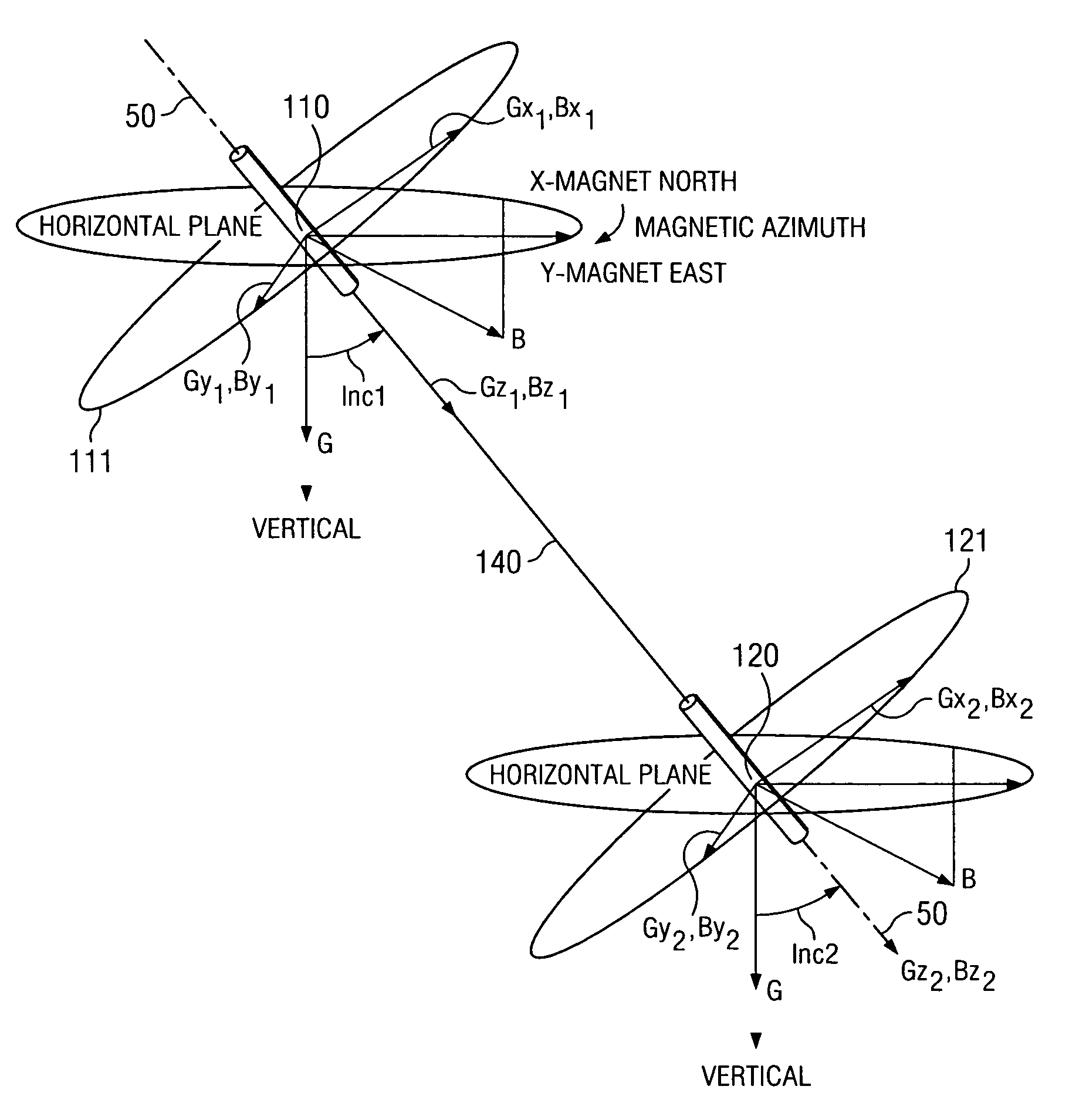
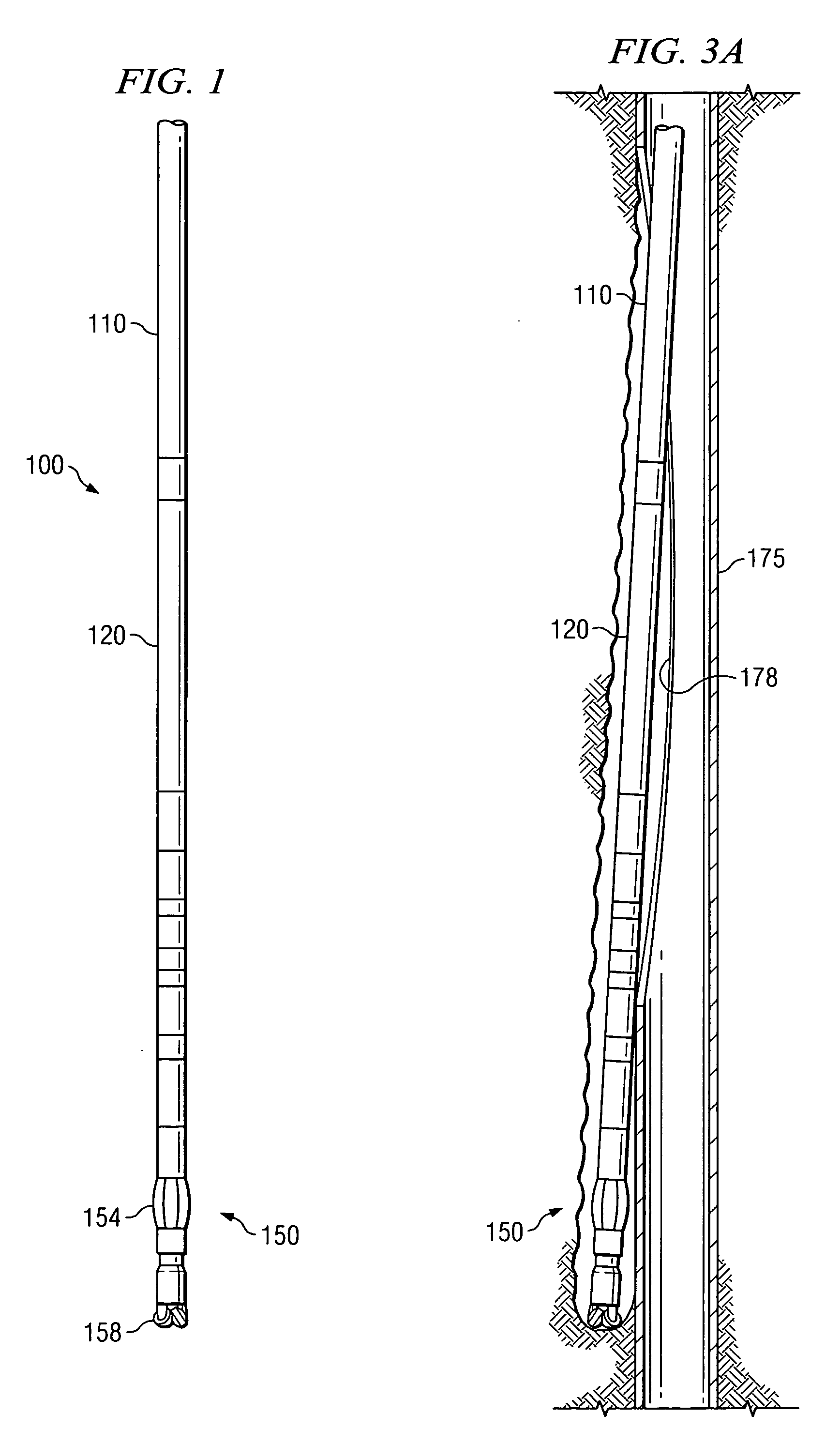
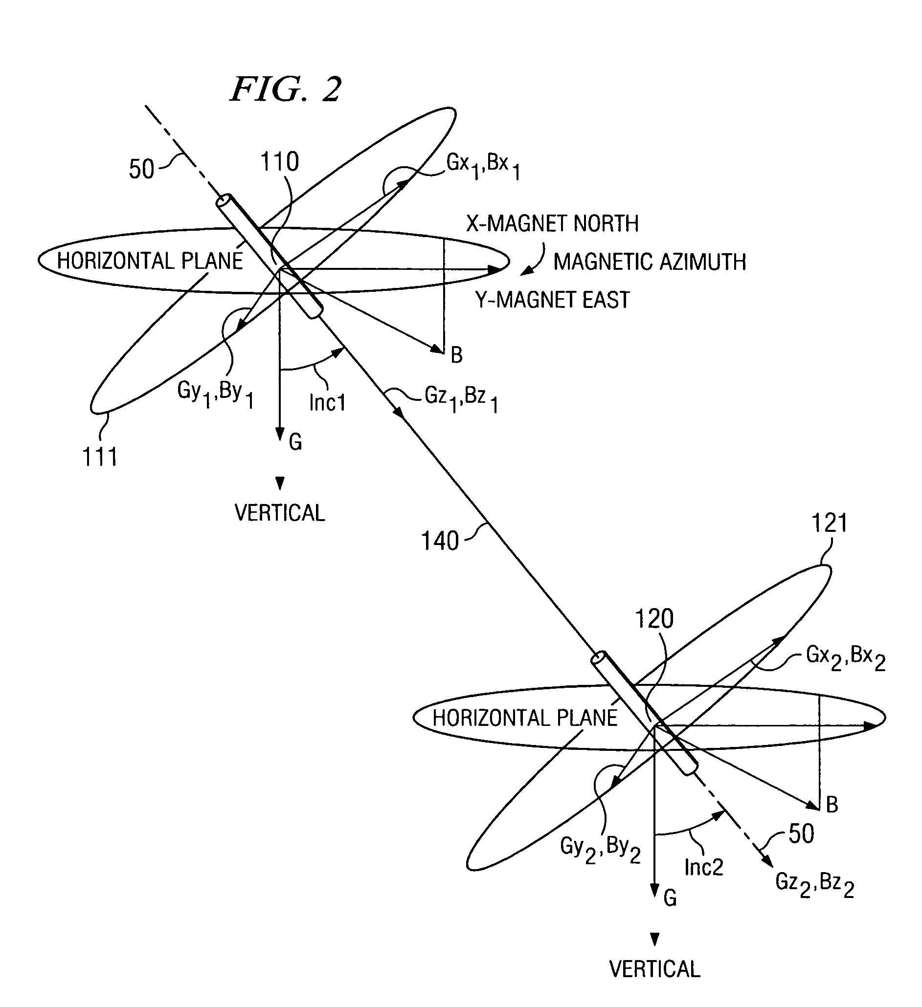
[0025]Referring now to FIG. 1, one exemplary embodiment of a downhole tool 100 useful in conjunction with the method of the present invention is illustrated. In FIG. 1, downhole tool 100 is illustrated as a measurement while drilling (MWD) tool including upper 110 and lower 120 sensor sets coupled to a bottom hole assembly (BHA) 150 including, for example, a steering tool 154 and a drill bit assembly 158. The upper 110 and lower 120 sensor sets are disposed at a known spacing, for example, on the order of from about 2 to about 20 meters (i.e., about 6 to about 60 feet). Each sensor set (110 and 120) includes at least two (and preferably three) mutually orthogonal magnetic field sensors, with at least one magnetic field sensor in each set having a known orientation with respect to the borehole, and three mutually orthogonal gravity sensors. It will be appreciated that the method of this invention may also be practiced with a downhole tool including only a single sensor set having at ...


PUM


Abstract

A method for surveying a borehole is provided. The method includes providing a tool having a magnetic field measurement device disposed thereon and positioning the tool in a borehole. Magnetic interference vectors are determined at at least two positions in the borehole by comparing the measured magnetic fields at those positions with a known magnetic field of the earth. The magnetic interference vectors indicate a direction to a target subterranean structure. Various embodiments of the invention compare the directions to the target subterranean structure with a historical survey thereof, so as to determine a distance between the borehole and the subterranean structure and an azimuth of the borehole. The surveying methodology of this invention may advantageously improve borehole surveying data obtained, for example, in relief well and / or well twinning drilling applications.

Description

RELATED APPLICATIONS[0001]This application claims priority to co-pending United Kingdom patent application no. 0313281.8, entitled WELL TWINNING TECHNIQUES IN BOREHOLE SURVEYING, filed Jun. 9, 2003.FIELD OF THE INVENTION[0002]The present invention relates generally to surveying a subterranean borehole to determine, for example, the path of the borehole. More particularly this invention relates to a method of passive ranging to determine directional and / or locational parameters of a borehole using sensors including one or more magnetic field measurement devices.BACKGROUND OF THE INVENTION[0003]The use of magnetic field measurement devices (e.g., magnetometers) in prior art subterranean surveying techniques for determining the direction of the earth's magnetic field at a particular point is well known. The use of accelerometers or gyroscopes in combination with one or more magnetometers to determine direction is also known. Deployments of such sensor sets are well known to determine b...

Claims


Application Information

Patent Timeline
IPC IPC(8): G01V3/26E21B47/022
CPCG01V3/26E21B47/022
Inventor MCELHINNEY, GRAHAM
Owner SCHLUMBERGER TECH CORP
Learn More