
Electrical switch system responsive to gear selection of vehicular transmission

a technology of electric switch and gear selection, applied in the direction of gearing control, gearing element, belt/chain/gearing, etc., can solve the problem of typical warpage and other problems

Active Publication Date: 2005-12-27
SENSATA TECH MASSACHUSETTS INC
View PDF8 Cites 9 Cited by
  • Summary
  • Abstract
  • Description
  • Claims
  • Application Information

AI Technical Summary

Benefits of technology

[0007]It is an object of the present invention to provide a switch system which overcomes the limitations of the prior art noted above. Another object of the invention is the provision of a switch system particularly useful with motor vehicle transmissions having a housing that overlies one face surface of the detent lever but does not extend beyond the opposite face surface of the detent lever in the vicinity of the movable contact assembly when in the DRIVE and LOW index positions. Yet another object of the invention is the provision of a switch system used with vehicular transmissions for providing an indication of transmission operation which is of low cost, robust, reliable and relatively insensitive to vibration.
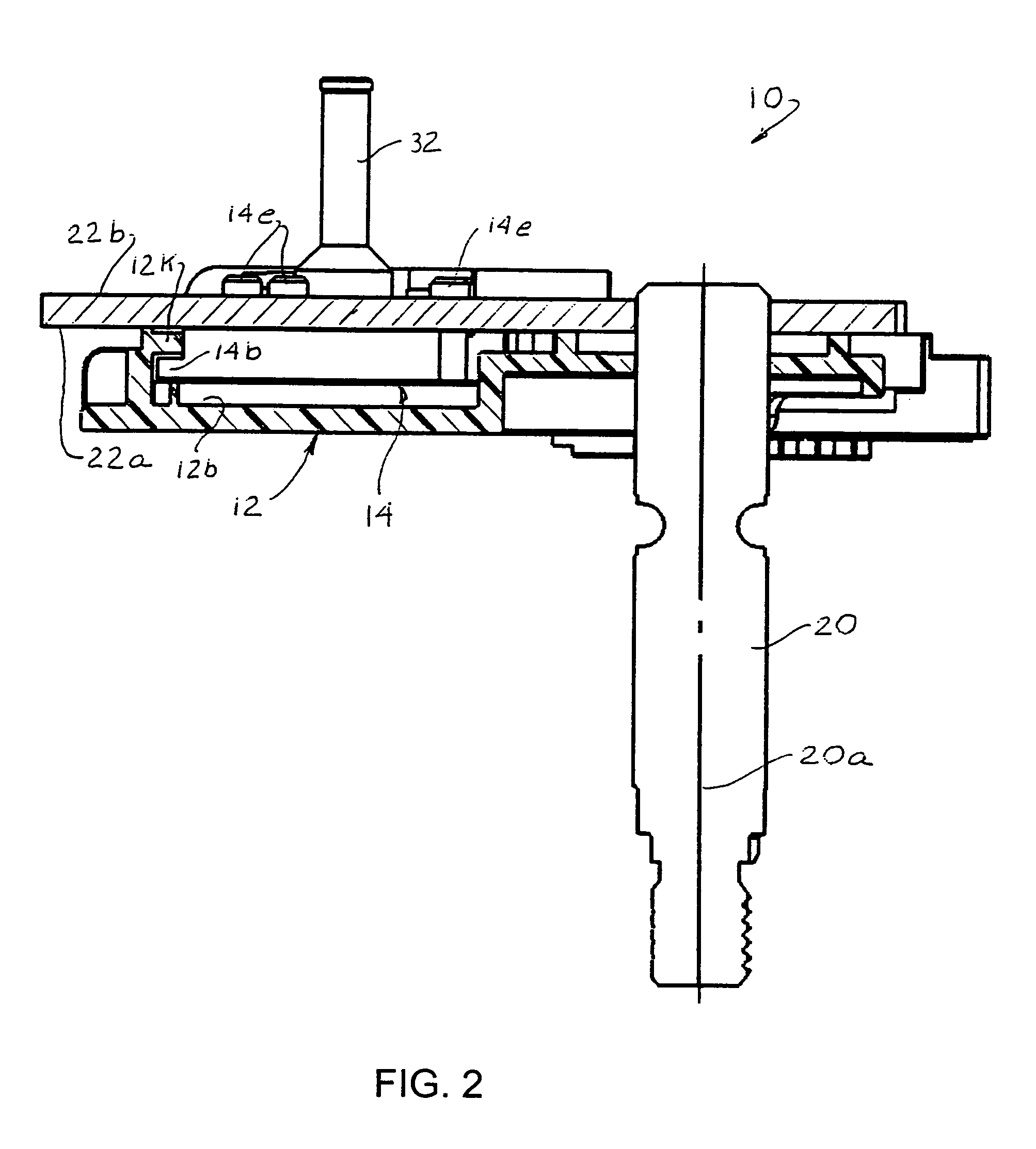
[0010]The housing is formed with a pair of spaced apart prongs between which the roller of a roller / spring assembly is used to maintain the housing in a selected x-y position as the detent lever and manual shaft pivot with changes of transmission position. The spacing between the movable contact assembly mounted on the insulative base member and the face surface of the housing on which the arcuate segments are exposed is closely controlled by the lip(s) of the insulative base member received in the control gap to thereby ensure continuous engagement of the movable contact assembly with the stationary contact assembly.

Problems solved by technology

Switch systems made in accordance with the '701 patent are very effective in obviating the prior art hostile environment and stack-up problems; however, in the transmission of certain vehicles the space available to place a switch system within the transmission housing, particularly in the direction taken along the longitudinal axis of the manual shaft, i.e., in a vertical or Z direction, is insufficient for housing structure of the switch system to extend beyond the second face surface of the detent lever in the vicinity of the arcuate stationary contacts, that is, L-shaped attachment projection 24a and leg 24d of the patent.
The problem of ensuring this maintenance of engagement is exacerbated by the fact that the switch system housing, molded of electrically insulative material, typically is subject to some degree of warpage.

Method used


Image

  • Electrical switch system responsive to gear selection of vehicular transmission
  • Electrical switch system responsive to gear selection of vehicular transmission
  • Electrical switch system responsive to gear selection of vehicular transmission

Examples


Embodiment Construction

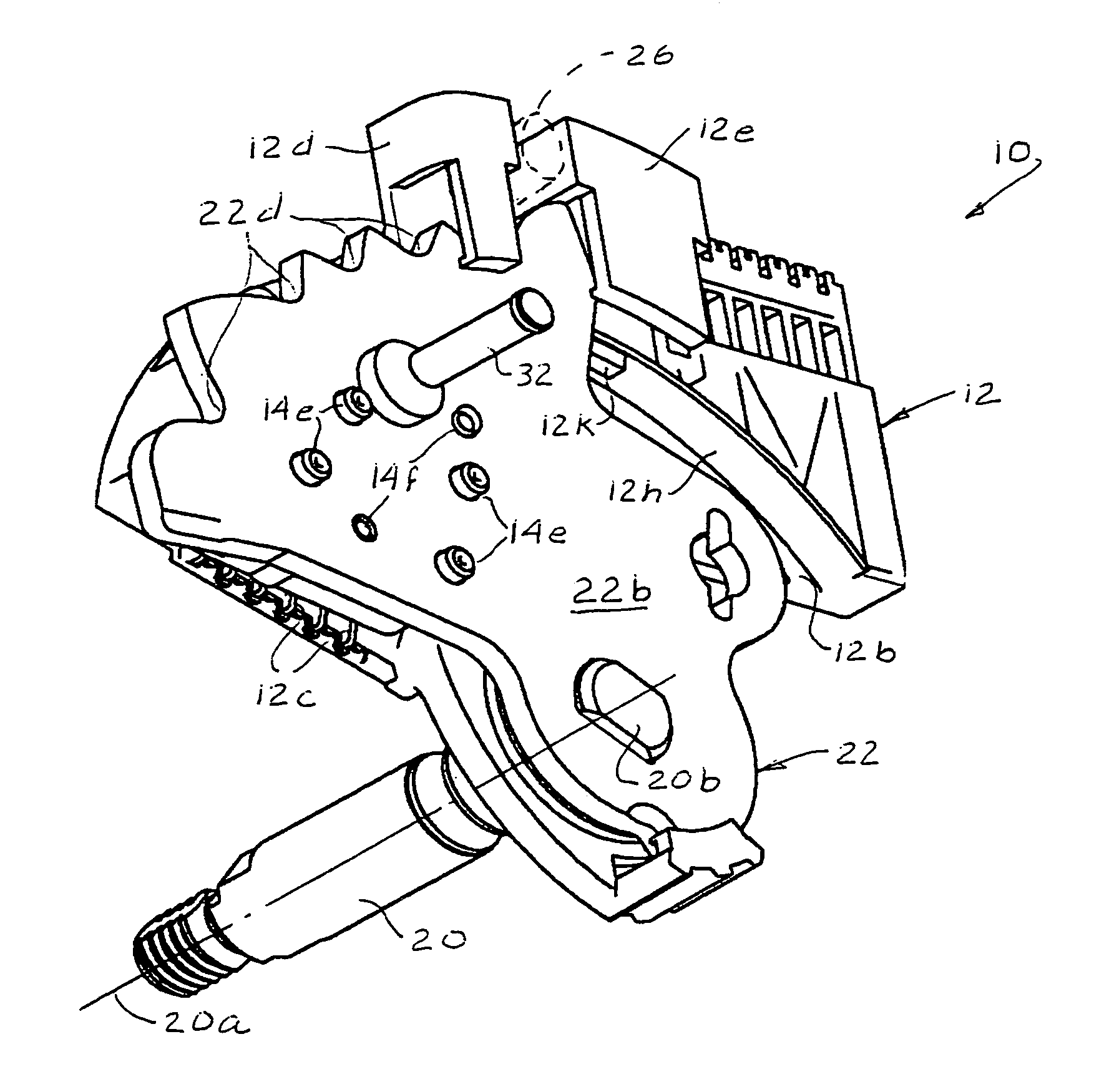
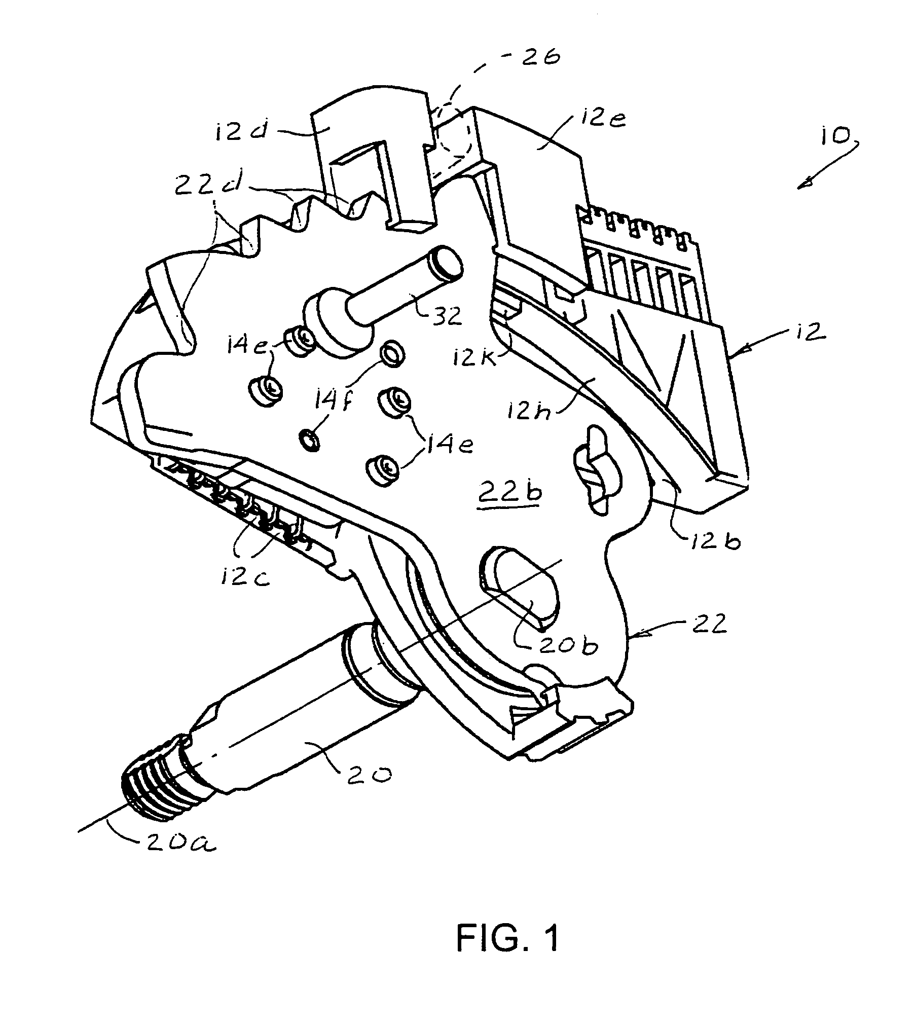
[0019]With reference to FIGS. 1–5, an electrical switch system 10 made in accordance with a preferred embodiment of the invention includes a housing 12 mounting a stationary contact assembly comprising a plurality of stationary contact segments 12a (FIG. 5) mounted on a manual shaft 20 for pivotable movement, relative to shaft 20, about longitudinal axis 20a of the shaft. Also mounted on manual shaft 20 is a detent lever 22 which is fixedly mounted on the shaft for pivotable motion with shaft 20 about longitudinal axis 20a. Detent lever 22 has opposed first and second generally planar face surfaces 22a, 22b with face surface 22a facing inner surface 12b of housing 12. An insulative base member 14 is fixedly attached to face surface 22a of detent lever 22. A movable contact assembly 16 is mounted on an outer surface 14a of base member 14 facing inner surface 12b of housing 12.

[0020]Detent lever 22 is fixed to manual shaft 20 so that detent lever 22 pivots along with the manual shaft ...


PUM


Abstract

An electrical switch system (10) for use with a motor vehicle transmission has a movable contact assembly (16) mounted on an insulative base member (14) in turn mounted on a detent lever (22). The detent lever (22) is mounted on a manual shaft (20) for pivotal movement therewith while a housing is rotatably mounted on the manual shaft facing the detent lever. A plurality of side-by-side arcuate contact strips are insert molded in the housing wall with contact segments (1–6) exposed on a wall facing the movable contact assembly. The housing is maintained in one fixed angular position while movable contacts sweep across the contact segments upon pivotal motion of the manual shaft. A control gap is provided by ledges (12k) formed in the housing with a lip (14b) of the insulative base member (14) mounting the movable contact assembly received in the control gap to ensure that appropriate contact engagement between the movable contact assembly and control segments is maintained. In a modified embodiment an additional lip (14b′) and corresponding housing ledge (12k′) is provided at an opposite side of the insulative base member.

Description

FIELD OF THE INVENTION[0001]This invention relates generally to vehicular transmissions and more particularly to an electrical switch system for providing a continuous signal to the transmission controller indicative of the position of the transmission.BACKGROUND OF THE INVENTION[0002]In past years it was common to mount a rotary switch on a transmission housing externally thereof to receive mechanical gear selection inputs from the operator of a vehicle through various linkages and output gear selections to appropriate output means such as a decoder module and the transmission electronic control unit via electronic signals. The switch includes a quadrant with a selected number of electrical switch segments disposed thereon with each segment providing an output to the output means. A manual valve controlling hydraulic operation of the transmission is mechanically coupled to a plate having indexing detents, called a detent lever, mounted on a shaft and pivotably movable therewith. Th...

Claims


Application Information

Patent Timeline
IPC IPC(8): F16H59/10H01H9/06H01H19/58
CPCF16H59/105H01H19/58H01H2300/02
Inventor BARBAGELATA, MELISSA M.HOUBRE, ANDREW K.
Owner SENSATA TECH MASSACHUSETTS INC
Learn More