
Downstream wind turbine

a wind turbine and downstream technology, applied in the field of wind turbines, can solve the problems of wind turbines being vulnerable to severe damage, runaway incidents, and adding chemical pollutants to the environmen

Inactive Publication Date: 2005-12-27
DRAKE DEVON GLEN
View PDF10 Cites 53 Cited by
  • Summary
  • Abstract
  • Description
  • Claims
  • Application Information

AI Technical Summary

Benefits of technology

[0022]It is an object of the invention to provide improved elements and arrangements thereof for the purposes described which is inexpensive, dependable and fully effective in accomplishing its intended purposes.

Problems solved by technology

Burning hydrocarbons both uses up valuable non-renewable resources and adds chemical pollutants to the environment.
However, wind turbines are vulnerable to severe damage caused by high winds.
Specifically, in high winds a wind turbine may experience a run-away incident in which the blades of the wind turbine rotate at a destructive rate.
Various expensive and complicated design solutions have been applied to wind turbines to avoid run-away incidents.
Since the brakes are typically applied when the rotor blades are near their maximum permitted rate of revolutions, failure in the braking system can lead to a run-away incident and the destruction of the wind turbine.
While such design solutions may help to avoid run-away incidents, rotating the turbine completely out of the wind stops the conversion of wind energy into electrical energy.
Rotating the turbine partially out of the wind creates additional stresses on the wind turbine.
The '629 solution is complex and relies on twisting a flexible beam, which must be designed to cope with such twisting thereby adding to manufacturing cost.
In addition to run-away issues, gyroscopic precession can cause severe loads on wind turbines.
Wind turbines not designed to handle precession risk serious damage.
Such design solutions are at best limited in scope and are not suitable for most areas where wind direction is variable.
Such mechanisms add to manufacturing and maintenance costs; in addition, a drive motor might be required to drive the mechanism.
Wind turbines fitted with such mechanisms are also less efficient since they are necessarily slow in responding to changes in wind direction.
Such wind turbines are very expensive to build since they require a considerable amount of strengthening and use of expensive parts.
In addition, the rotator blades will experience severe flexing forces necessitating expensive development and high manufacturing costs.
Teetering blades can strike the support tower destroying the turbine.

Method used


Image

  • Downstream wind turbine
  • Downstream wind turbine
  • Downstream wind turbine

Examples


Embodiment Construction

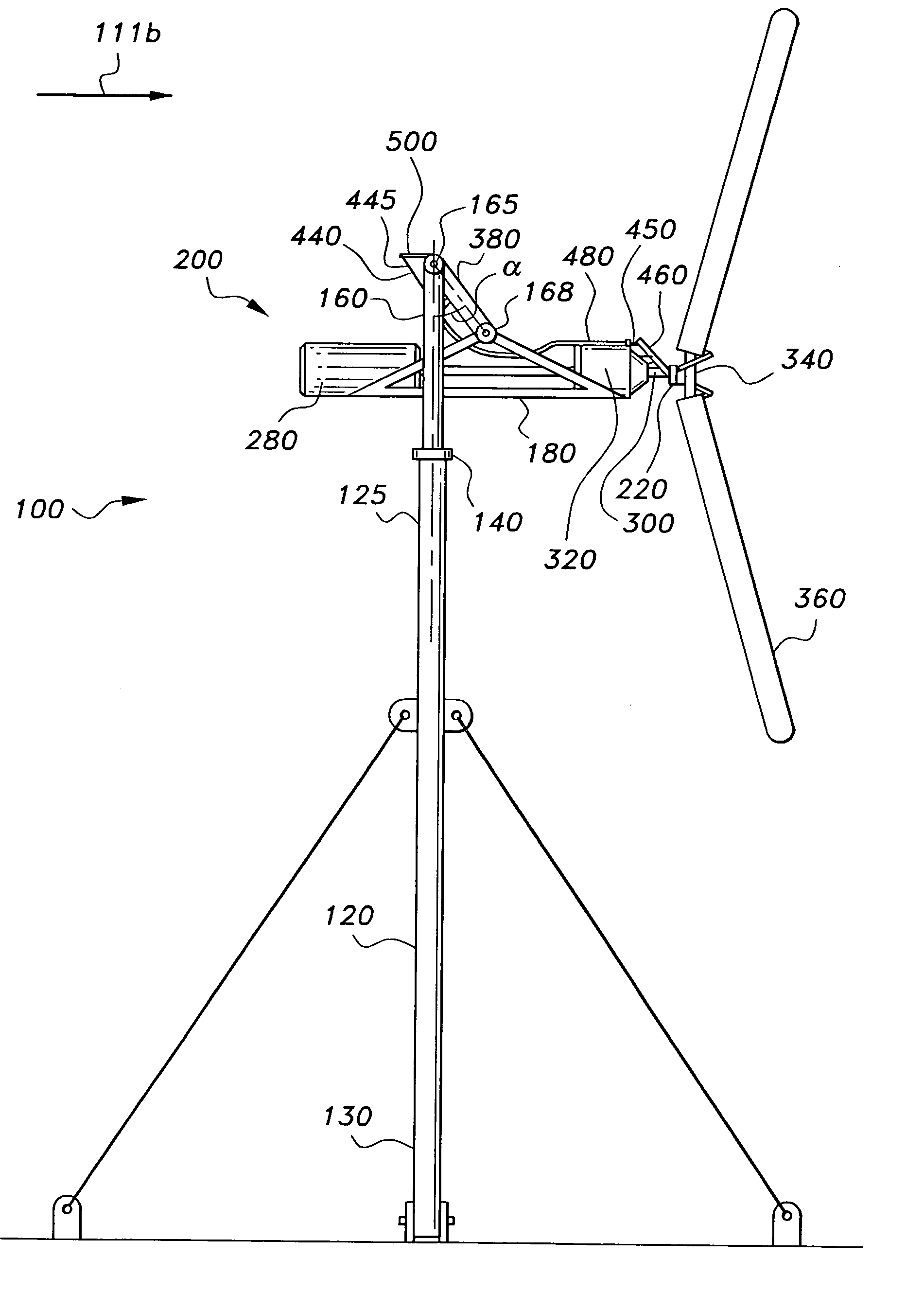
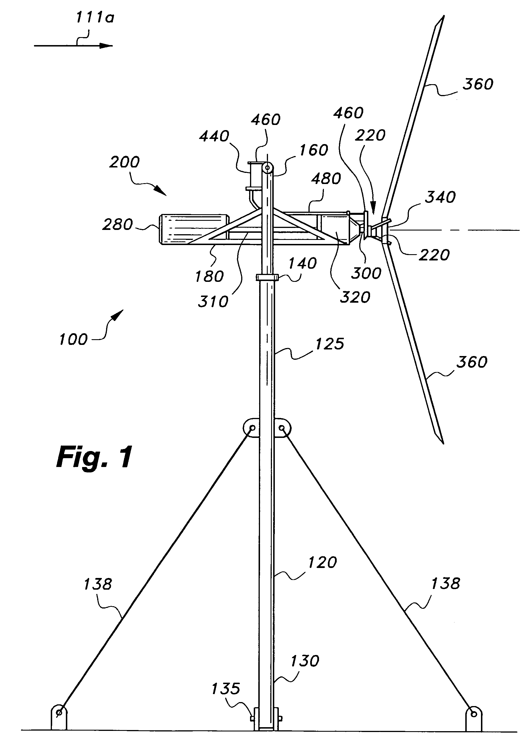
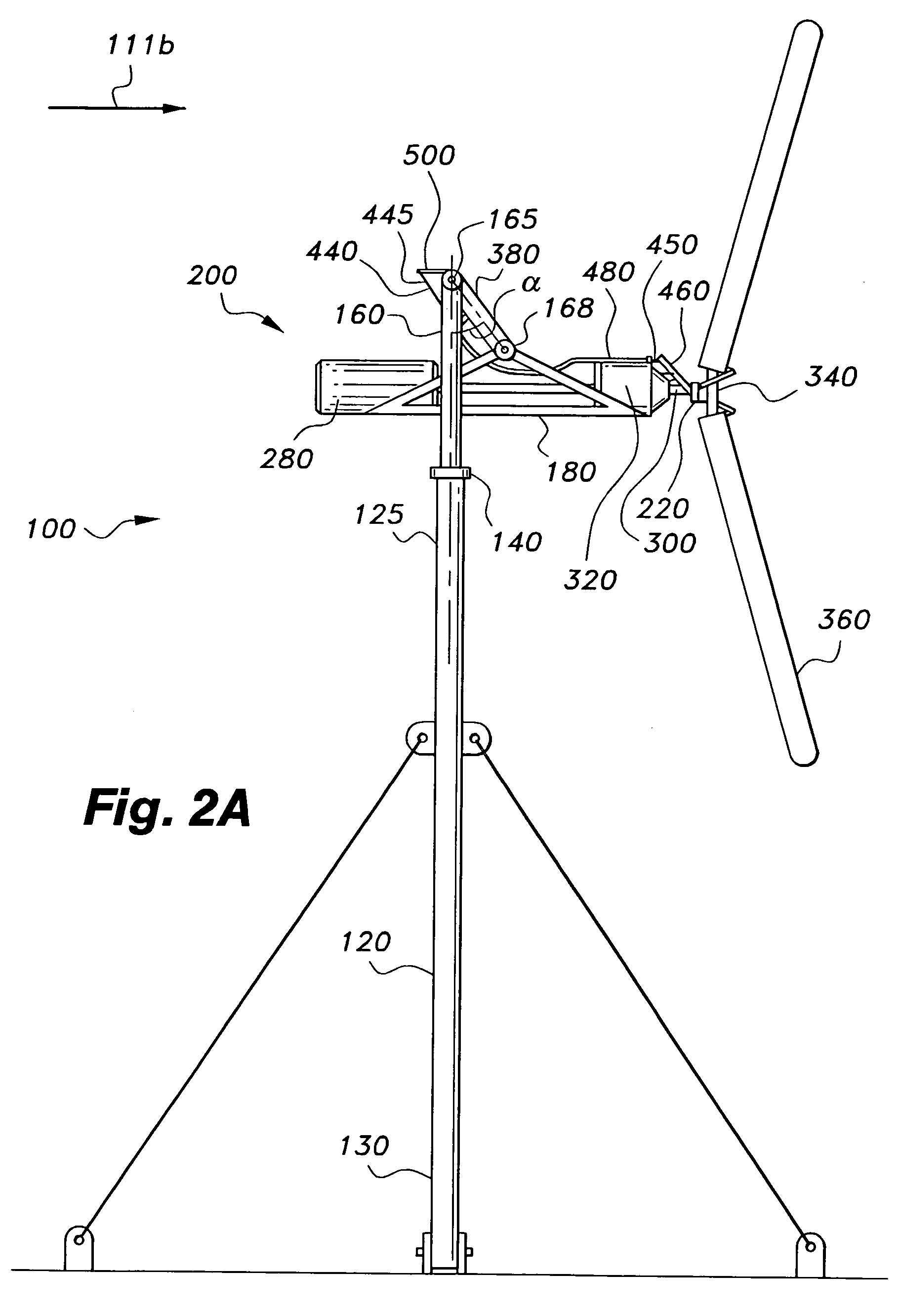
[0041]The present invention is directed to a downstream wind turbine for converting wind energy into electrical energy and, more specifically, to a downstream wind turbine 100 adapted to respond to high winds and gyroscopic precession.

[0042]FIG. 1 is side view of a downstream wind turbine 100 according to the present invention. The downstream wind turbine 100 is shown operating in ambient wind conditions. Wind condition and direction are represented by alpha-numeral “111a”.

[0043]Still referring to FIG. 1, the downstream wind turbine 100 comprises an approximately vertical support tower 120 having a top 125 and bottom 130, a yaw bearing 140 attached to the top 125 of the tower 120, a support frame 160, an elongated carry member 180 pivotally attached to the support frame 160, wherein the carry member is free to swing away and downstream from the support tower 100 or support frame 160 (see FIG. 2A), a wind driven energy conversion system 200 balanced on and firmly attached to the car...


PUM


Abstract

A downstream wind turbine for converting wind energy into electrical energy. In a preferred embodiment the downstream wind turbine adapted to respond to high winds and gyroscopic precession. The downstream wind turbine comprises a support tower; a yaw bearing attached to the support tower; a support frame operably linked to the bearing; at least one swing arm with one end pivotally attached to the support frame; an elongated carry member pivotally attached to the other end of the swing arm; a wind driven energy conversion system balanced on and attached to the carry member so that the carry member is biased to maintain an approximately horizontal orientation with respect to the support frame and in response to wind proportionally swings downstream, and which responds to gyroscopic precession forces by tilting up or down; and a governor device for modifying at least one dynamic characteristic of the turbine.

Description

CROSS-REFERENCE TO RELATED APPLICATIONS[0001]The present application is a continuation-in-part of U.S. patent application Ser. No. 10 / 271,982 filed on Oct. 17, 2002, now abandoned; patent application Ser. No. 10 / 271,982 is incorporated by reference herein in its entirety.STATEMENT REGARDING FEDERALLY SPONSORED RESEARCH OR DEVELOPMENT[0002]Not Applicable.BACKGROUND OF THE INVENTION[0003]This invention relates to a wind turbine for generating electrical power.[0004]Conventional power generating plant, such as coal and oil fired plant, use hydrocarbon fuels to generate electricity. Burning hydrocarbons both uses up valuable non-renewable resources and adds chemical pollutants to the environment. Thus there is a need to harness natural energy for conversion into electrical energy.[0005]Natural energy sources include water, in the form of hydroelectric power, and wind. Hydroelectric power is available in areas with favorable geography such as found in Norway where hydroelectric power mak...

Claims


Application Information

Patent Timeline
Patent Type & Authority Patents(United States)
IPC IPC(8): F03D1/00F03D7/00
CPCF03D1/00F03D7/02F05B2240/2022F05B2240/2213Y02E10/723Y02E10/72
Inventor DRAKE, DEVON GLEN
Owner DRAKE DEVON GLEN
Learn More