
Shift control apparatus and method for automated twin clutch transmission

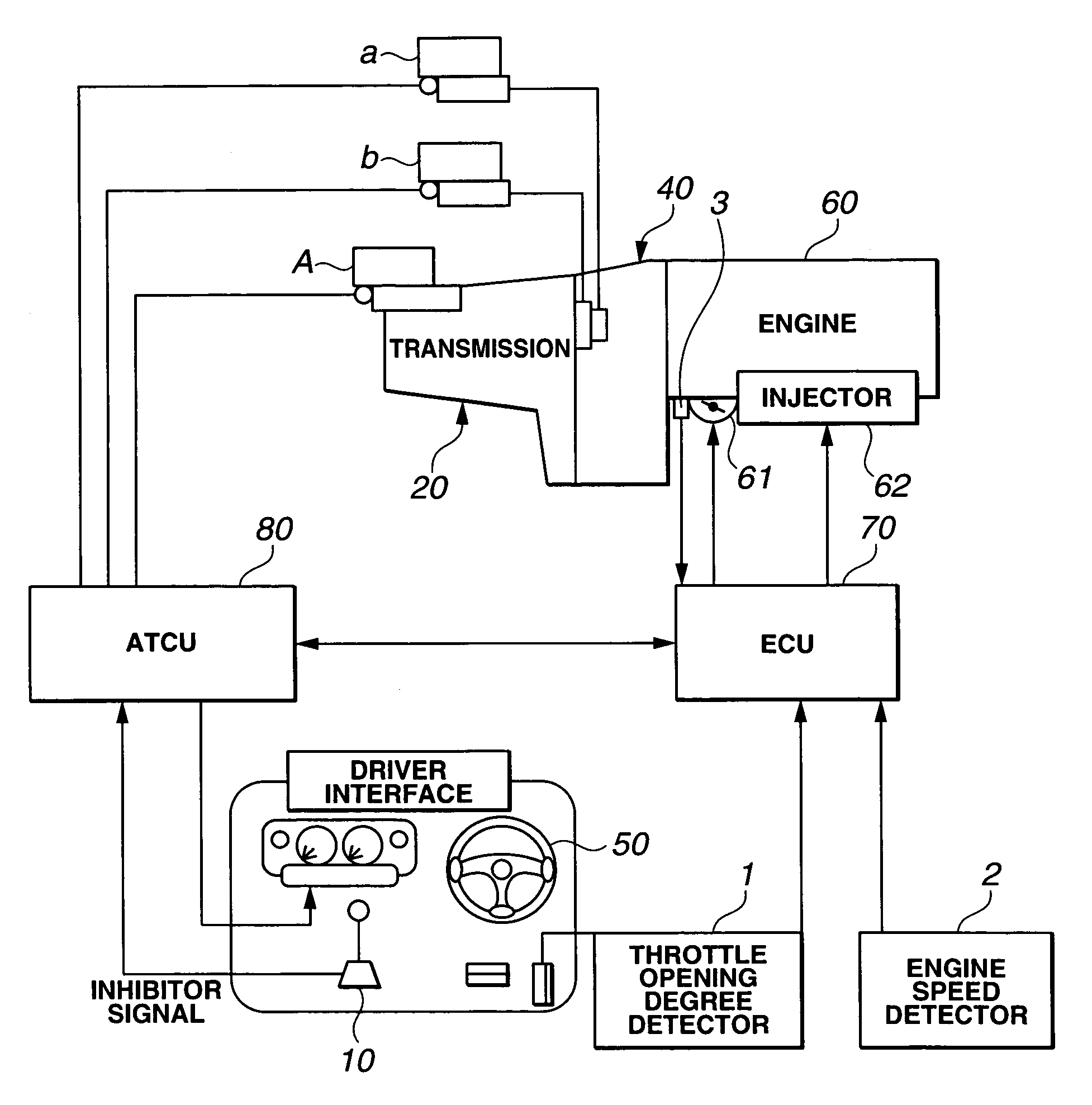
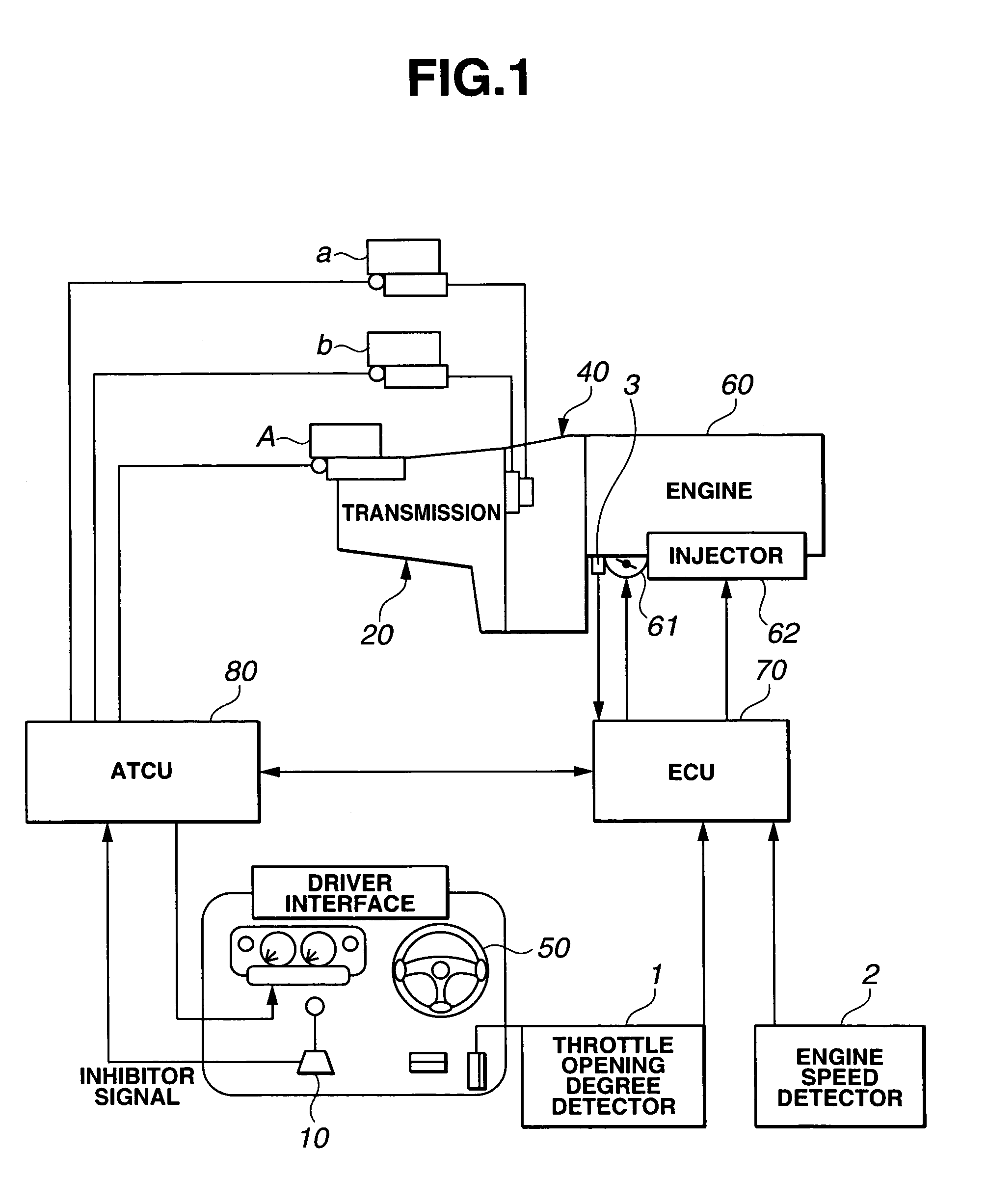
Active Publication Date: 2005-12-27
NISSAN MOTOR CO LTD
View PDF5 Cites 16 Cited by
  • Summary
  • Abstract
  • Description
  • Claims
  • Application Information

AI Technical Summary

Benefits of technology

[0004]It is accordingly an object of the present invention to provide a shift control apparatus for an automated twin clutch transmission that can prevent a response delay at the time of gearshift.

Problems solved by technology

In the above-described control, the time necessary for the pre-shift control results in a response delay which gives a strange or embarrassed feel to a vehicle driver.

Method used


Image

  • Shift control apparatus and method for automated twin clutch transmission
  • Shift control apparatus and method for automated twin clutch transmission
  • Shift control apparatus and method for automated twin clutch transmission

Examples


second embodiment

[0076](Second Embodiment)

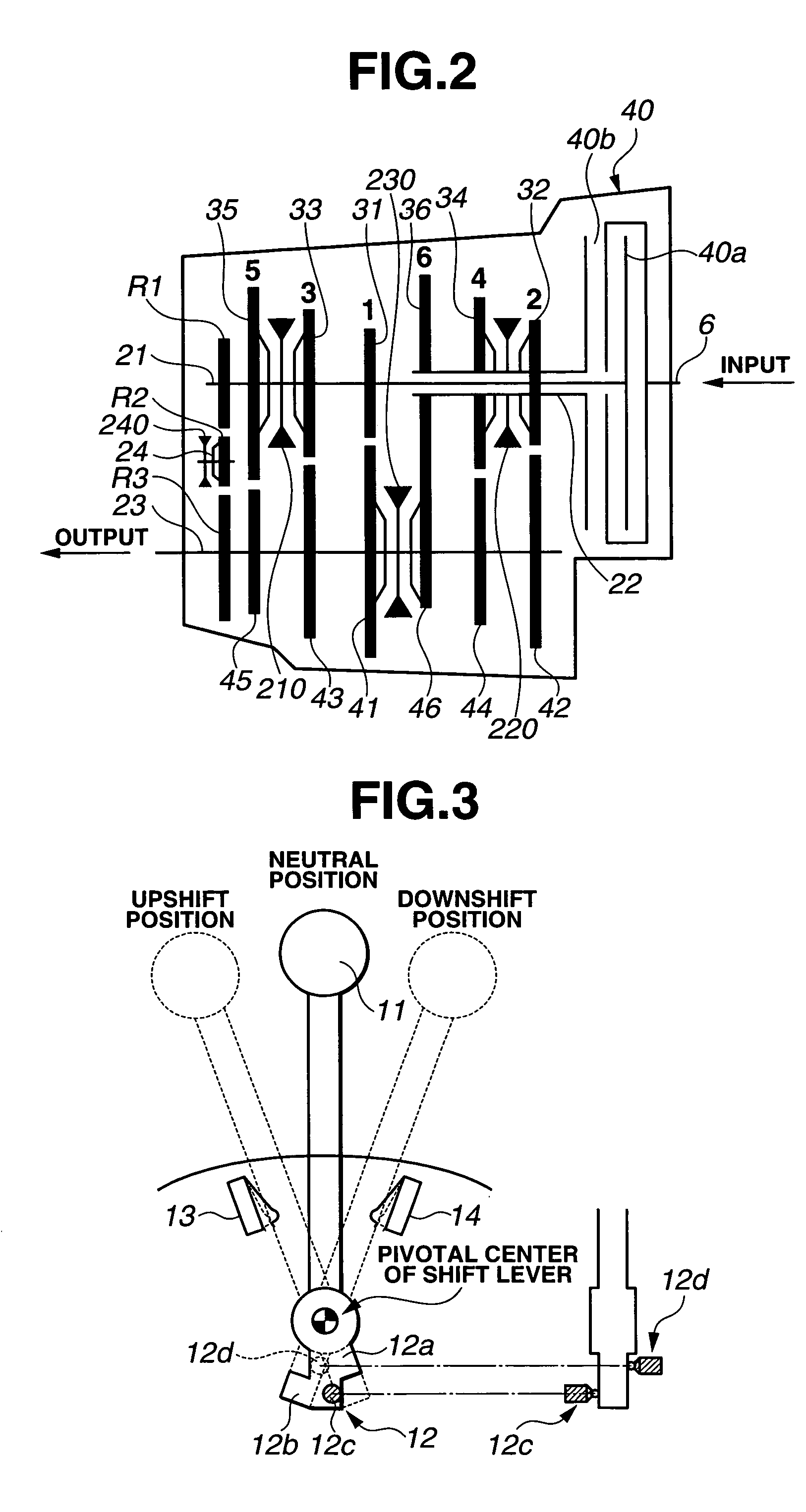
[0077]FIG. 6 shows a shift mechanism that is operated by a driver upon shifting according to a second embodiment which is basically the same as the first embodiment so that only a different structure will be described.

[0078]In the second embodiment, potentiometer 121 is provided to serve as a means for detecting a shift position. By detecting the shift position of shift lever 11 by potentiometer 121, the intension of the vehicle driver can be detected promptly without delay.

third embodiment

[0079](Third Embodiment)

[0080]FIG. 7 shows a shift mechanism that is operated by a vehicle driver upon shifting according to a third embodiment which is basically the same as the first embodiment so that only a different structure will be described.

[0081]In the third embodiment, stroke sensor 122 is provided as a means for detecting a shift position. By detecting the shift position of shift lever 11 by stroke sensor 122, the intension of the vehicle driver can be detected promptly without delay.

fourth embodiment

[0082](Fourth Embodiment)

[0083]FIG. 8 shows a shift mechanism that is operated by a vehicle driver upon shifting according to a fourth embodiment which is basically the same as the first embodiment so that only a different structure will be described.

[0084]In the fourth embodiment, hole element sensor 123 is provided as a means for detecting a shift position. By detecting the shift position of shift lever 11 by hole element sensor 123, the intension of the driver can be detected promptly without delay.


PUM


Abstract

A shift control apparatus for an automated twin clutch transmission includes a shifting movement detecting device operable to detect start of shifting movement of a shift instructing device and output a shift starting instruction, and a shift controller configured to perform, in response to the shift starting instruction, a pre-shift control by releasing one of the first and second engine clutches from a power transmission route of a pre-shift gear ratio and engaging one of the shift clutches corresponding to a post-shift gear ratio, and perform, in response to a shift instruction form a shift instruction outputting device, a gearshift by releasing the other of the first and second engine clutches from the power transmission route of the pre-shift gear ratio and engaging the above-mentioned one of the first and second engine clutches. A shift control method is also provided.

Description

BACKGROUND OF THE INVENTION[0001]The present invention relates in general to transmissions for motor vehicles and more particularly to a shift control apparatus and method for an automated twin clutch transmission capable of shifting automatically in response to a shift instruction from a shift mechanism.[0002]Japanese Unexamined Patent Publication No. 2001-295898 discloses an automated twin clutch transmission including two power transmission routes consisting of two input shafts and a plurality of synchronous meshing type gearsets. The transmission further includes two engine clutches each disposed between an engine and each input shaft for controlling transmission of a drive torque therebetween. In such a transmission, a clutch engagement and disengagement control and a gear selection control are performed automatically.SUMMARY OF THE INVENTION[0003]The above-described shift control apparatus has the following problem. Namely, in the above-described shift control apparatus, a gea...

Claims


Application Information

Patent Timeline
IPC IPC(8): F16H61/10F16H59/02F16H61/02F16H61/688
CPCF16H59/0204F16H61/0206F16H61/688F16H2061/0216F16H2306/18Y10T74/19233F16H2306/50F16H2059/0239F16H2059/0247Y10T74/19251F16H2306/46
Inventor KATAKURA, TAKEJI
Owner NISSAN MOTOR CO LTD
Learn More