
Internet co-location facility security system

a security system and colocation technology, applied in the field of security systems, can solve problems such as access denied

Inactive Publication Date: 2005-12-13
EQUINIX
View PDF16 Cites 68 Cited by
  • Summary
  • Abstract
  • Description
  • Claims
  • Application Information

AI Technical Summary

Benefits of technology

This solution provides enhanced security integration, improved access control, and efficient visitor management, allowing co-located members to monitor visitor locations in real-time across multiple facilities, reducing security risks and operational burdens.

Problems solved by technology

If there is no match, access is denied.

Method used


Image

  • Internet co-location facility security system
  • Internet co-location facility security system
  • Internet co-location facility security system

Examples


Embodiment Construction

[0023]Throughout the following description specific details are set forth in order to provide a more thorough understanding of the invention. However, the invention may be practiced without these particulars. In other instances, well known elements have not been shown or described in detail to avoid unnecessarily obscuring the present invention. Accordingly, the specification and drawings are to be regarded in an illustrative, rather than a restrictive, sense.

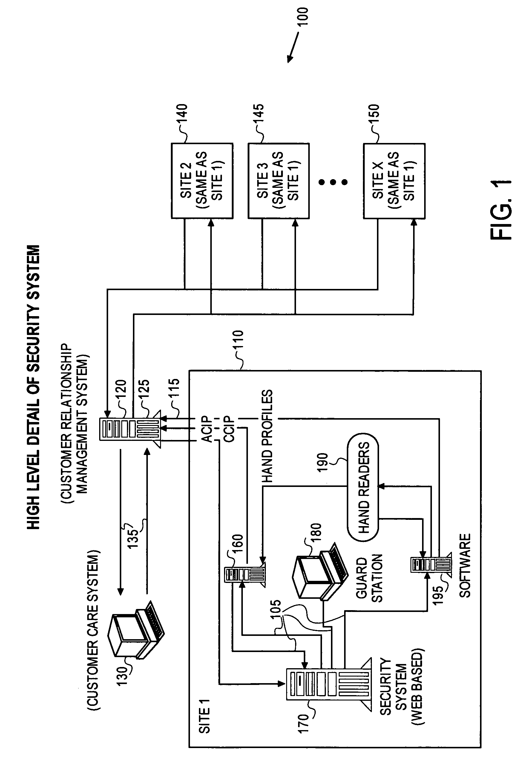
[0024]Referring now to FIG. 1, there is shown a functional block diagram illustrating the overall operation of an Internet co-location facility security system 100 in accordance with one embodiment of the present invention. The Internet co-location facility 110 itself may include a facility comprising a plurality of cabinets located in shared or private cages (not shown in this view). Each cabinet is an enclosed frame or cage into which equipment may be mounted. The cabinets may be configured in full spaces (for example 36″ dee...


PUM


Abstract

An Internet co-location facility security system integrates all the major components of the system and makes tracking information from these components available to co-located members on a database accessible from the web. A web-based interface allows co-located members to assign visitor access to the Internet co-location facility through the Internet from remote computer terminals. A visitor access and enrollment system allows a visitor to enroll only once in the system to be granted access to one or more other Internet co-location facility security systems around the globe.

Description

FIELD OF THE INVENTION[0001]The present invention relates generally to the field of security systems and, more particularly, to an Internet co-location facility security system.BACKGROUND[0002]The growing use of the Internet by businesses around the globe is creating a need for a scalable and secure home for every organization with a mission critical Internet component. Various facilities exist to provide Internet Service Providers (ISPs), Application Service Providers (ASPs), and content providers with a safe place to house their hardware.[0003]In a typical co-location model, member sites are placed in an environment where they have access to a network provider, site management and web hosting arrangements, and other similar types of services. While co-location models expedite electronic transmissions, the clustering of member sites in these facilities makes them vulnerable to vandals, thieves, and even terrorist attacks. Because modern e-commerce companies moving billions of dolla...

Claims


Application Information

Patent Timeline
Patent Type & Authority Patents(United States)
IPC IPC(8): G06F11/30G06F12/14G06F21/00G07C9/00H04L9/00H04L9/32H04L29/06
CPCG06F21/32G06F21/41G07C9/00087G07C9/00103H04L63/105H04L63/107G07C9/257G07C9/27
Inventor AVERY, IV, ALBERT M.ADELSON, JAY STEVENVOGT, DERRALD CURTIS
Owner EQUINIX
Learn More