
Variable resolution digital calibration

a digital calibration and variable resolution technology, applied in the direction of digital computer details, instruments, code conversion, etc., can solve the problems of electronic components, precision in one or more signals provided by electronic components, and electronic devices that rely on closeness, etc., to be vulnerable to errors caused

Active Publication Date: 2005-12-13
ANALOG DEVICES INC
View PDF7 Cites 21 Cited by
  • Summary
  • Abstract
  • Description
  • Claims
  • Application Information

AI Technical Summary

Benefits of technology

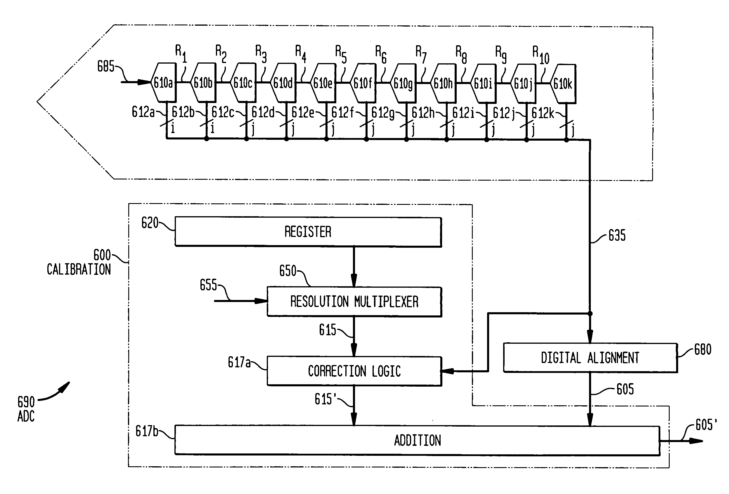
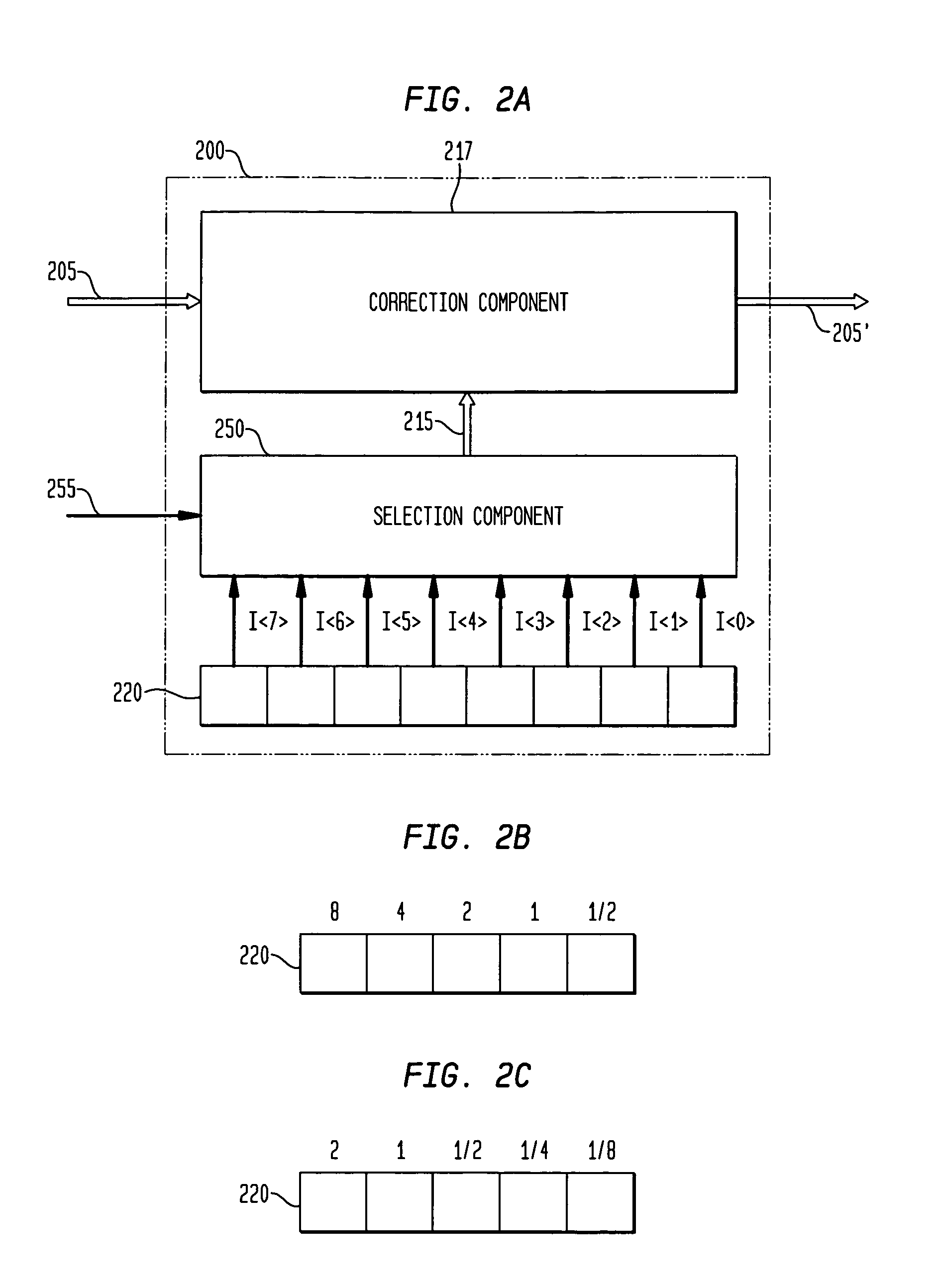
The present invention provides a method, apparatus, and computer-readable media for calibrating signals of an electronic device. The method involves assigning calibration bits to a bit weight configuration to provide calibration information with a selected resolution, and applying the calibration information to the signals to provide calibrated signals. The apparatus includes a register for storing calibration bits, a selection component for assigning bit weight configurations to the calibration bits, and a correction component for adjusting the signals based on the calibration information. The technical effect of the invention is to improve the accuracy and reliability of signals in electronic devices.

Problems solved by technology

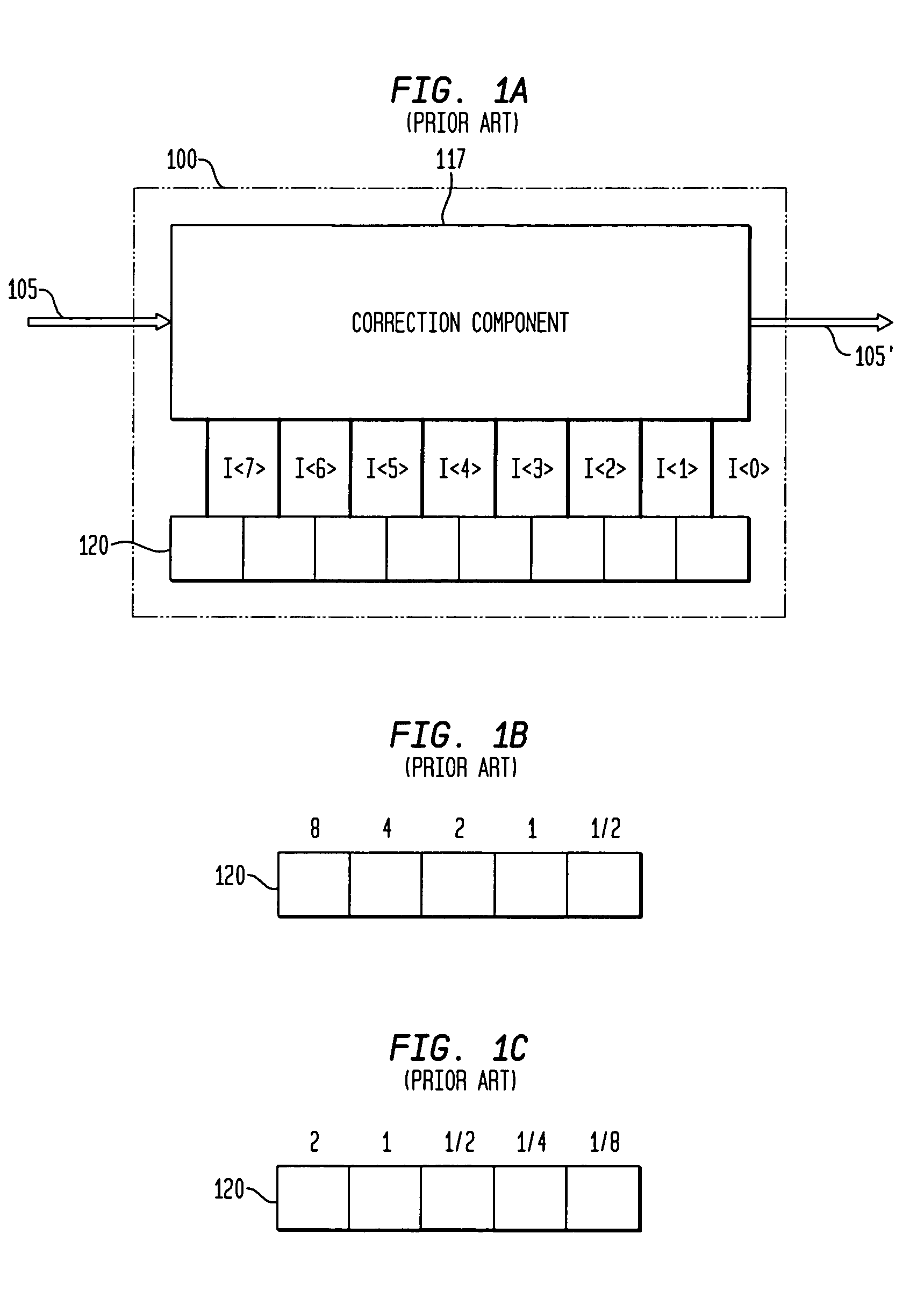
Electronic devices that rely on the close matching of electronic components (e.g., resistors, capacitors, etc.) or precision in one or more signals provided by an electronic component may be vulnerable to errors caused by tolerances inherent in the manufacture of the components.
Such imperfectly matched components may provide one or more signals having errors in proportion to the mismatch.
However, increasing the number of fuses (and / or increasing the size of the memory) increases the size of the device, for example, by increasing the die area of an integrated circuit.
In addition, the larger the memory, the more power the device consumes.
As a result, there is often a tradeoff between die area and power consumption, and the resolution at which a device may be calibrated.

Method used


Image

  • Variable resolution digital calibration
  • Variable resolution digital calibration
  • Variable resolution digital calibration

Examples


Embodiment Construction

[0022]Many digital and / or analog devices operate by generating, responding to and / or operating on one or more signals. The signals within a device may be digital signals, analog signals or a combination of both. The performance of a device may depend in part on the accuracy or precision of the signals being generated, operated on or output by the device. As discussed above, there are numerous influences that may effect the accuracy of a signal. For example, component mismatch, component imprecision and / or various signal processing imprecision may effect the accuracy of one or more signals of an electronic device. Various calibration techniques have been employed to correct for these errors such that an electronic device operates with satisfactory accuracy and precision.

[0023]Errors in one or more signals of a device are often determined during part-by-part testing. For example, after an electronic device has been manufactured, testing equipment may be employed to determine the exten...


PUM


Abstract

Methods and apparatus for calibrating one or more signals of an electronic device are provided. Calibration coefficients are stored in a memory, such as a fuse bank, to be applied to correct the one or more signals. A selection multiplexer is provided, the selection multiplexer capable of assigning one of a number of bit weight configurations to the calibration coefficients to set a desired range and resolution for calibration information applied to the one or more signals of the electronic device.

Description

FIELD OF THE INVENTION[0001]The present invention relates generally to calibrating analog and / or digital components and, more particularly to calibrating an analog-to-digital converter (ADC) such as, for example, a multi-stage or pipeline ADC.BACKGROUND OF THE INVENTION[0002]Electronic devices that rely on the close matching of electronic components (e.g., resistors, capacitors, etc.) or precision in one or more signals provided by an electronic component may be vulnerable to errors caused by tolerances inherent in the manufacture of the components. Calibration is often performed on a device to reduce or eliminate these errors. The term “calibrate” refers generally to any modification to a signal and / or electronic component to provide correction and / or compensation. For example, calibration may include adjusting one or more signals to correct for component mismatch errors.[0003]Analog-to-digital converters (ADC), for example, often employ one or more sample and hold circuits that re...

Claims


Application Information

Patent Timeline
Patent Type & Authority Patents(United States)
IPC IPC(8): H03M1/10H03M1/12
CPCH03M1/1038H03M1/12
Inventor BARDSLEY, SCOTT G.
Owner ANALOG DEVICES INC
Learn More