
Hub motor mechanism

a technology of hub motor and hub, which is applied in the direction of cycle equipment, optical signal, gearing, etc., can solve the problems of inconvenient practical use of hub, waste of electric power of electric motor, and insatisfactory efficiency of hub rotation

Inactive Publication Date: 2005-12-13
LO CHIU HSIANG
View PDF10 Cites 109 Cited by
  • Summary
  • Abstract
  • Description
  • Claims
  • Application Information

AI Technical Summary

Benefits of technology

"The present invention is about an electric hub that has a motor inside it. The motor has two fixed shafts and drives a gear system. The hub is supported by a board with planet gears that match with the gear system. The hub can rotate relative to the motor. The invention allows for easy driving of the hub using a gear ring that matches with the sub-gears. The technical effect of this invention is to provide a simple and efficient way to drive an electric hub."

Problems solved by technology

Nevertheless, the lack of better speed changing system for the conventional hub motor, electrical motor wastes too much electric power and the efficiency of the rotation of the hub is not satisfied.
Although a planetary gear system is used in these inventions, the lack of the use of electrical motor makes the hub be inconvenient in practical use.

Method used


Image

  • Hub motor mechanism
  • Hub motor mechanism
  • Hub motor mechanism

Examples


Embodiment Construction

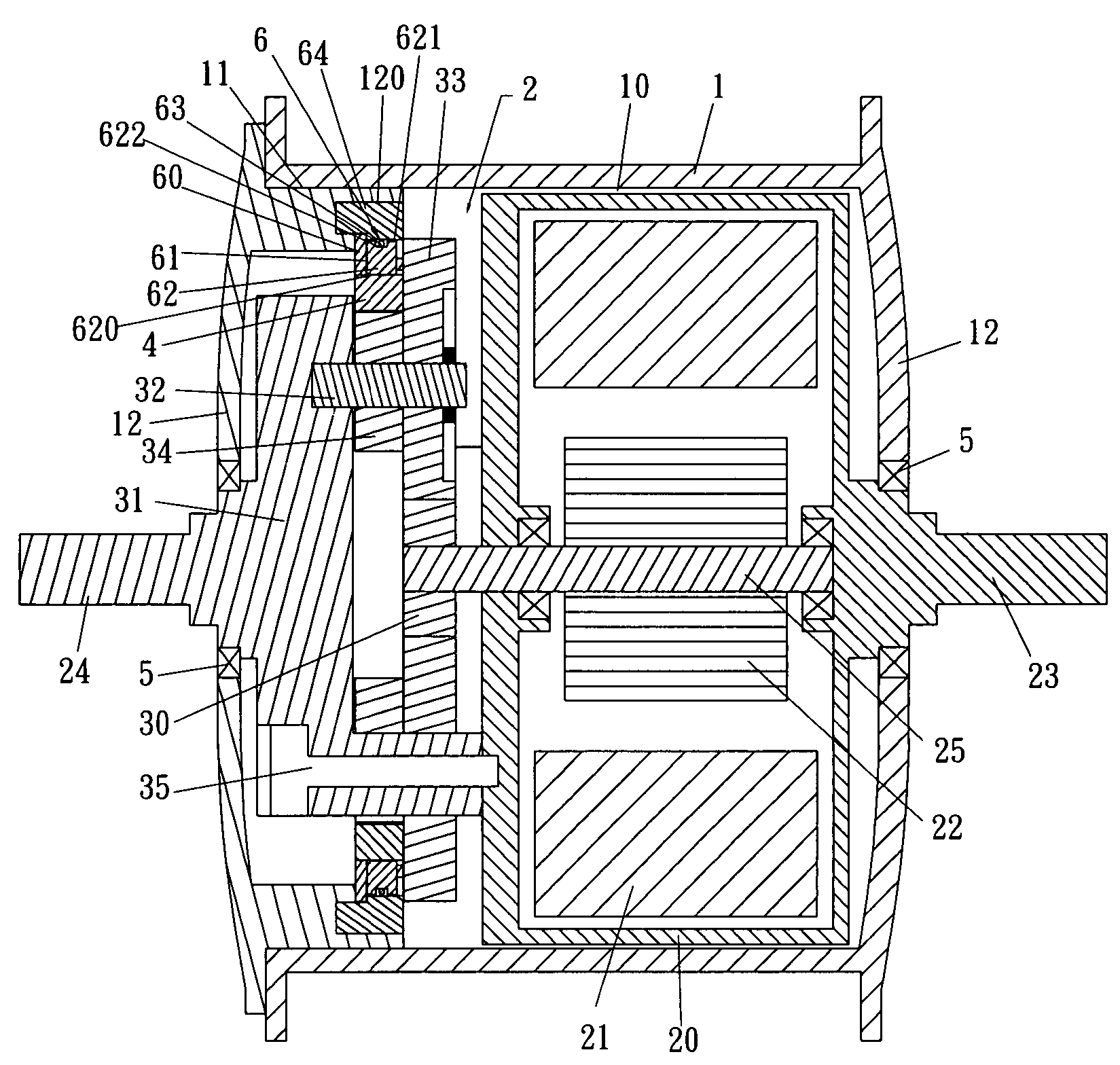
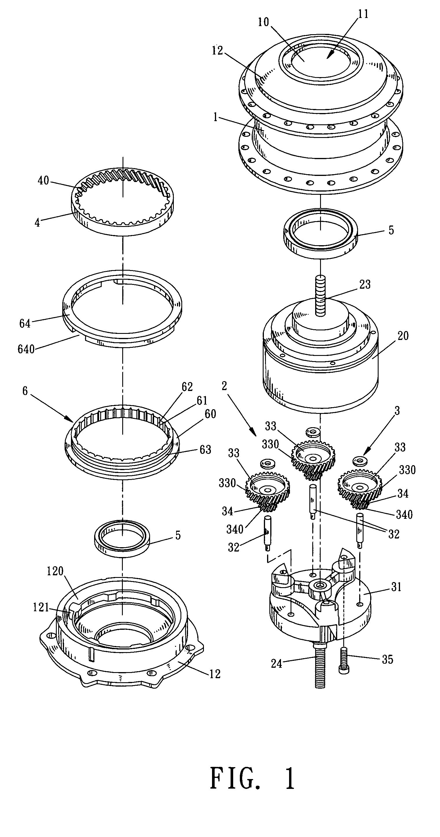
[0012]Referring to FIGS. 1 to 5, the electrically driven hub of the present invention comprises a hub 1 having a chamber 10 defined therein and a cover 12 is connected to an open side 11 of the hub 1 to seal the chamber 10. An electrical mechanism 2 is received in the chamber 10 so as to drive the hub 1 and comprises an electrical motor 20 which includes a stator 21 and a rotor 22 which is rotated relative to the stator 21. A first fixed shaft 23 is connected to a first end of the stator 21 and a second fixed shaft 24 is connected to a second end of the stator 21. An output shaft 25 is connected to the rotor 22 and drives a planetary gear system 3. The fixed shaft 23, the second shaft 24 and the output shaft 25 share a common axis.

[0013]The planetary gear system 3 has a sun gear 30 which is mounted to the output shaft 25. A support board 31 is fixed to the stator 21 and the second fixed shaft 24 is connected to the support board 31. The first fixed shaft 23 extends from an end of th...


PUM


Abstract

An electrically driven hub includes an electrical mechanism including an electrical motor and a planetary gear system connected to the electrical mechanism. A first fixed shaft is connected to the stator of the electrical motor and a second fixed shaft is connected to a second end of the stator of the electrical motor. The first and second fixed shafts are connected to the vehicle frame. A one-way clutch is connected between a cover of the hub and the planetary gear system so that the hub is rotated when the planetary gear system is activated by the motor.

Description

FIELD OF THE INVENTION[0001]The present invention relates to a hub motor mechanism for driving a wheeled vehicle such as a bicycle or a wheelchair, and the transmission system of the hub motor is efficient and has low noise.BACKGROUND OF THE INVENTION[0002]A conventional hub motor is disclosed in U.S. Pat. No. 6,321,863 and includes an electrical motor received in a hub which is driven by the electrical motor. Nevertheless, the lack of better speed changing system for the conventional hub motor, electrical motor wastes too much electric power and the efficiency of the rotation of the hub is not satisfied. Some alternative inventions for the hub motors are disclosed in U.S. Pat. No. 4,294,138 and 5,273,500. Although a planetary gear system is used in these inventions, the lack of the use of electrical motor makes the hub be inconvenient in practical use.[0003]The present invention intends to provide a hub assembly which is driven by an electrical motor. A planetary gear system is con...

Claims


Application Information

Patent Timeline
Patent Type & Authority Patents(United States)
IPC IPC(8): A61G5/04B62M7/12F16H1/28
CPCB62M7/12A61G5/04F16H1/28B60L15/2054B60L2200/12B60L2200/34B60L2220/44B60L2220/50Y02T10/72B60L50/20Y02T10/64
Inventor LO, CHIU-HSIANG
Owner LO CHIU HSIANG
Learn More