
Using fluids at elevated temperatures to increase fracture gradients

a technology of fracture gradient and fluid, which is applied in the direction of survey, wellbore/well accessories, insulation, etc., can solve the problems of limiting the depth of the casing, limiting the dynamic pressure maximum, and blowing out of the well, so as to reduce the diameter, increase the fracture gradient in the wellbore, and prevent the loss of drilling fluid

Inactive Publication Date: 2005-12-13
HALLIBURTON ENERGY SERVICES INC
View PDF7 Cites 7 Cited by
  • Summary
  • Abstract
  • Description
  • Claims
  • Application Information

AI Technical Summary

Benefits of technology

The patent text describes a method for drilling a wellbore in a formation using a drilling fluid to increase fracture gradients. The method involves determining fracture gradients at different depths in the wellbore and increasing the temperature of the drilling fluid to an elevated temperature at the last casing shoe. The elevated temperature can be set to a super-static temperature. The method can be used to increase the safety and efficiency of drilling the wellbore.

Problems solved by technology

If not properly controlled, this influx may lead to a blowout of the well.
Therefore, the formation fracture pressure typically defines an upper limit for allowable wellbore pressure in an open wellbore.
Thus, the maximum dynamic pressure allowable tends to be limited by the fracture pressure.
The fracture pressures may limit the depth of the casing strings to be set below the casing shoe of the first initial casing string.
Drawbacks to this technique using circulating drilling fluid temperatures lower than static temperature include the fact that a large number of casing strings are required to be set in the wellbore.
The number of casing strings tends to increase the cost of drilling the well.
Such reduction in size limits the size of the equipment that can be passed through the casing string.

Method used


Image

  • Using fluids at elevated temperatures to increase fracture gradients
  • Using fluids at elevated temperatures to increase fracture gradients
  • Using fluids at elevated temperatures to increase fracture gradients

Examples


third embodiment

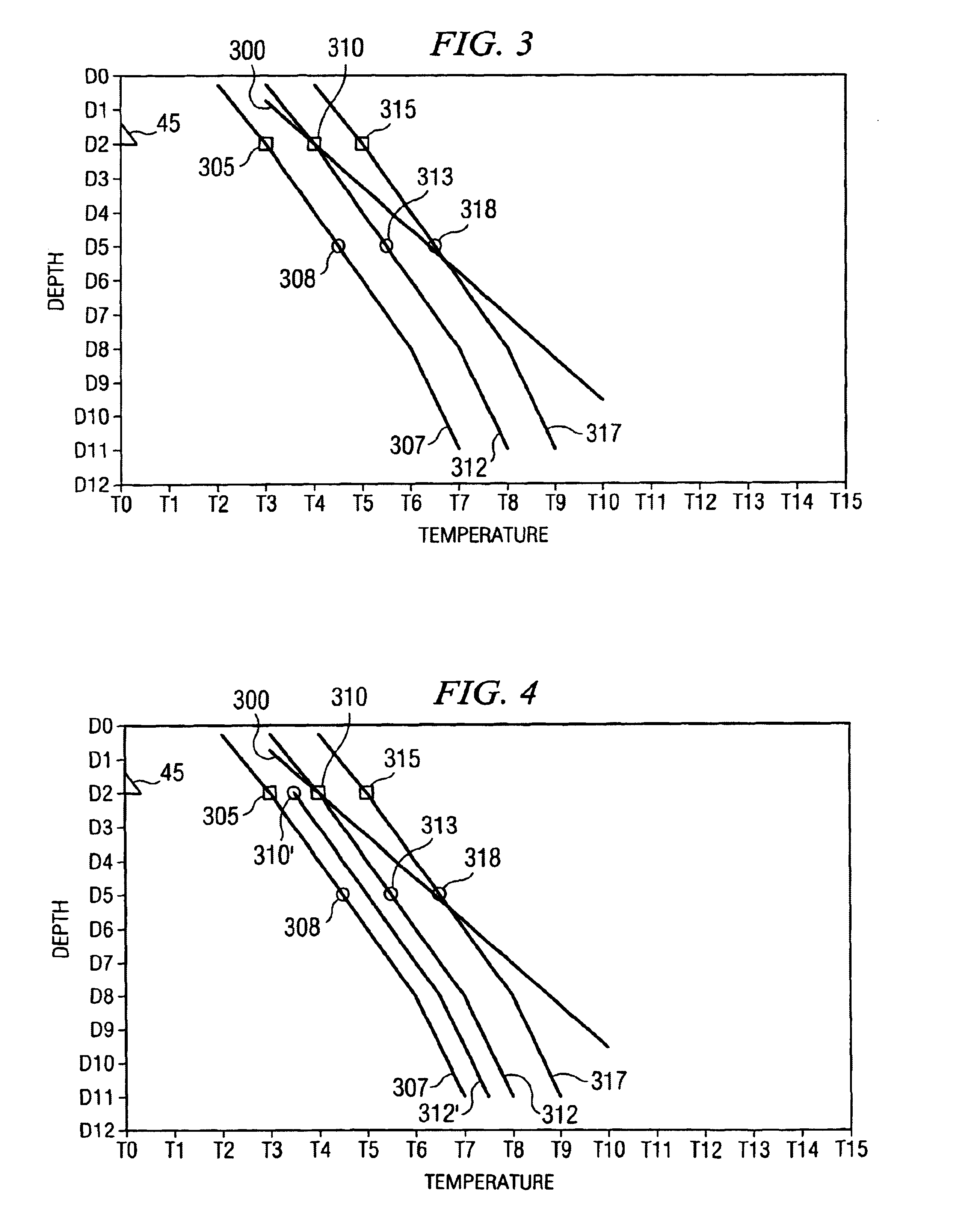
[0014]In a third embodiment, the invention provides for a method for drilling a wellbore in a formation using a drilling fluid, wherein a last casing string and a last casing shoe are disposed in the wellbore, wherein the drilling fluid has a first temperature, the method comprising: (A) increasing the temperature of the drilling fluid to a desired temperature at about the last casing shoe; (B) determining at least one fracture gradient at the desired temperature, wherein the fracture gradient is determined at about the last casing shoe; (C) drilling into the formation at increasing wellbore depths below the last casing shoe, wherein at least one equivalent circulating density of the drilling fluid is calculated at about the last casing shoe; and (D) setting a next casing string at a depth at which the equivalent circulating density is about equal to or within a desired range of a fracture gradient determined at about last casing shoe.

fourth embodiment

[0015]In a fourth embodiment, the invention provides for a method for drilling a wellbore in a formation using a drilling fluid to increase fracture gradients, wherein a last casing string and a last casing shoe are disposed in the wellbore, the method comprising: (A) determining at least one fracture gradient at about the last casing shoe, wherein an initial fracture gradient is determined at a conventional drilling fluid temperature, (B) drilling into the formation below the last casing shoe at increasing depths with the drilling fluid at about the conventional drilling fluid temperature at about the last casing shoe, and wherein at least one equivalent circulating density of the drilling fluid is determined at about the last casing shoe; (C) increasing the temperature of the drilling fluid at about the last casing shoe to an elevated drilling fluid temperature; (D) drilling further into the wellbore at increasing depths with the drilling fluid at about the elevated temperature at...

fifth embodiment

[0016]In a fifth embodiment, the invention provides for a method for drilling a wellbore in a formation using a drilling fluid to increase fracture gradients, wherein a last casing string and a last casing shoe are disposed in the wellbore, wherein the drilling fluid has a first temperature, the method comprising: (A) increasing the temperature of the drilling fluid to an elevated temperature at about the last casing shoe; (B) determining at least one fracture gradient at about the last casing shoe, wherein at least one elevated fracture gradient is determined; (C) drilling into the formation below the last casing shoe at increasing depths with the drilling fluid at about the elevated temperature at about the last casing shoe, and wherein at least one equivalent circulating density of the drilling fluid is determined at about the last casing shoe; (D) increasing the temperature of the drilling fluid at about the last casing shoe to a super-static temperature; (E) drilling further in...


PUM

PropertyMeasurementUnit
depthsaaaaaaaaaa
temperatureaaaaaaaaaa
circulating densityaaaaaaaaaa

Abstract

A method for drilling a wellbore in a formation using a drilling fluid, wherein the drilling fluid has a first temperature, and wherein the wellbore has a first wellbore depth. In one embodiment, the method comprises determining at least one fracture gradient, wherein the fracture gradient is determined at about the first wellbore depth; increasing the temperature of the drilling fluid from the first temperature to a desired temperature at about the first wellbore depth; drilling into the formation at increasing wellbore depths below the first wellbore depth, wherein at least one equivalent circulating density of the drilling fluid is determined at about the first wellbore depth; and setting a casing string at a depth at which the equivalent circulating density is about equal to or within a desired range of the fracture gradient. In other embodiments, an automated system is used to maintain the temperature of the drilling fluid at about first wellbore depth.

Description

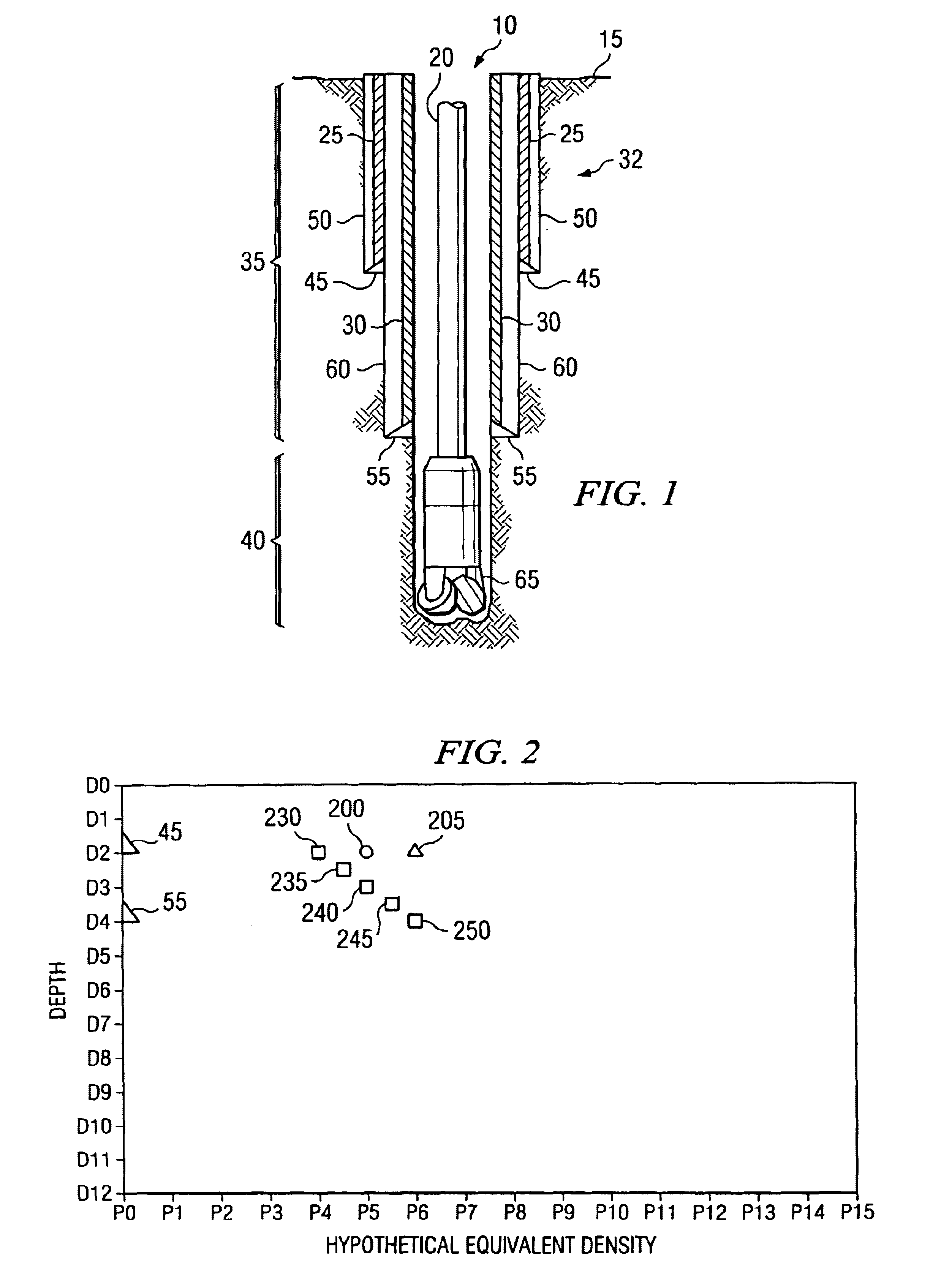
BACKGROUND OF THE INVENTION[0001]1. Field of the Invention[0002]This invention relates to the field of drilling wellbores and more specifically to the field of using drilling fluids at elevated temperatures to increase fracture gradients in a wellbore.[0003]2. Background of the Invention[0004]In the drilling industry, a drilling fluid is typically used when drilling a wellbore. The drilling fluid may be used to provide pressure in the wellbore, clean the wellbore, cool and lubricate the drill bit, and the like. The wellbore may comprise a cased portion and an open portion. The open portion extends below the last casing string, which may be cemented to the formation above a casing shoe. In standard operations, the drilling fluid is circulated into the wellbore through the drill string. The drilling fluid returns to the surface through the annulus between the wellbore wall and the drill string. The pressure of the drilling fluid flowing through the annulus acts on the open wellbore. T...

Claims


Application Information

Patent Timeline
Patent Type & Authority Patents(United States)
IPC IPC(8): E21B
CPCE21B21/06E21B21/08E21B36/00E21B7/00
Inventor NAQUIN, CAREY J.
Owner HALLIBURTON ENERGY SERVICES INC
Learn More