High pressure discharge vessel for an alumina high-intensity discharge lamp

a discharge lamp and high-intensity technology, which is applied in the manufacture of electric discharge tubes/lamps, cold cathode manufacture, electrode systems, etc., can solve the problems of physical strength decline and possible cracks, and achieve the effects of increasing physical strength, reducing physical strength, and minimizing crack generation

Inactive Publication Date: 2005-11-29
NGK INSULATORS LTD
View PDF18 Cites 2 Cited by
  • Summary
  • Abstract
  • Description
  • Claims
  • Application Information

AI Technical Summary

Benefits of technology

[0009]We, the inventors, have studied the sintering characteristics of a ceramic where the diameter of grains in the ceramic becomes greater at higher sintering temperatures, thus decreasing the physical strength and where the diameter of grains in the ceramic becomes smaller at lower sintering temperatures, thus increasing the physical strength. As a result, an improved discharge vessel or chamber of a capillary type was developed which minimized the generation of cracks. According to the present invention, a discharge vessel or chamber for a high-intensity discharge lamp having a central body arranged providing a discharge space therein and two capillaries provided for closing off both end openings of the body and accepting a pair of electrodes, respectively, is provided, wherein the central body and the capillaries are made of an alumina material or an alumina-based ceramic material and the average diameter of alumina grains in the capillaries ranges from 10 micrometers to 25 micrometers.

Problems solved by technology

As the discharge vessel or chamber of such a conventional capillary type is baked at a high temperature for increasing the permeability of light across its body, the physical strength tends to decline.
In particular, when the capillary is joined and sealed with the electrode, it may possibly crack.
However, controlling the amount of the frit sealer requires a highly precise technique while increasing the thickness of the capillary interrupts the down-sizing of a resultant discharge lamp.

Method used


Image

  • High pressure discharge vessel for an alumina high-intensity discharge lamp
  • High pressure discharge vessel for an alumina high-intensity discharge lamp
  • High pressure discharge vessel for an alumina high-intensity discharge lamp

Examples


second embodiment

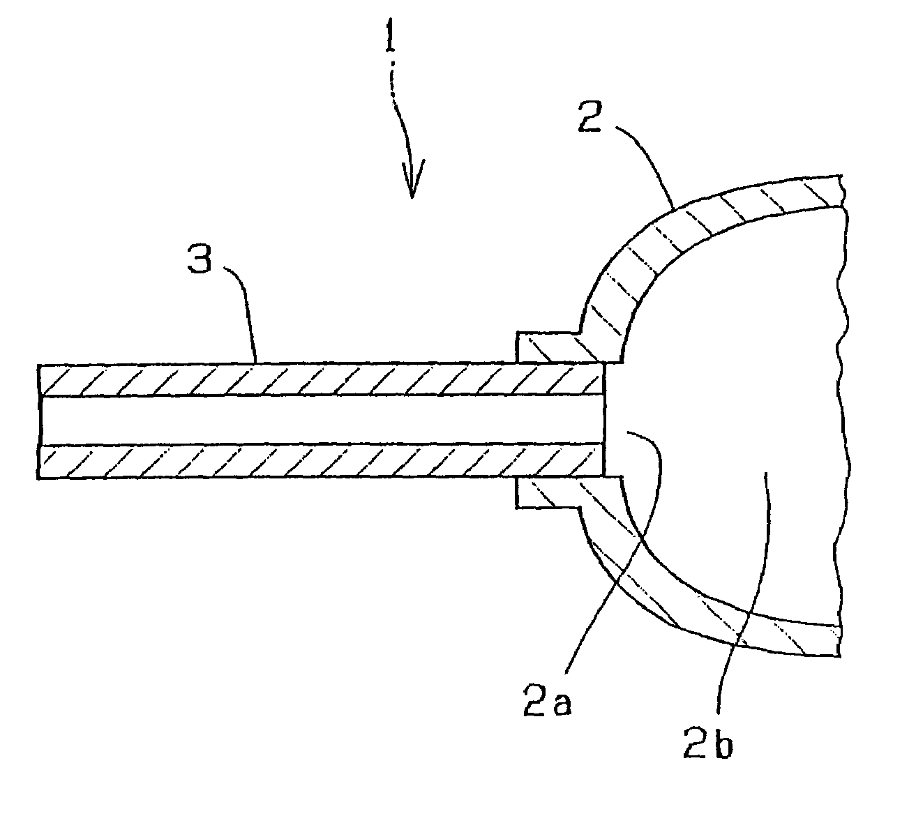
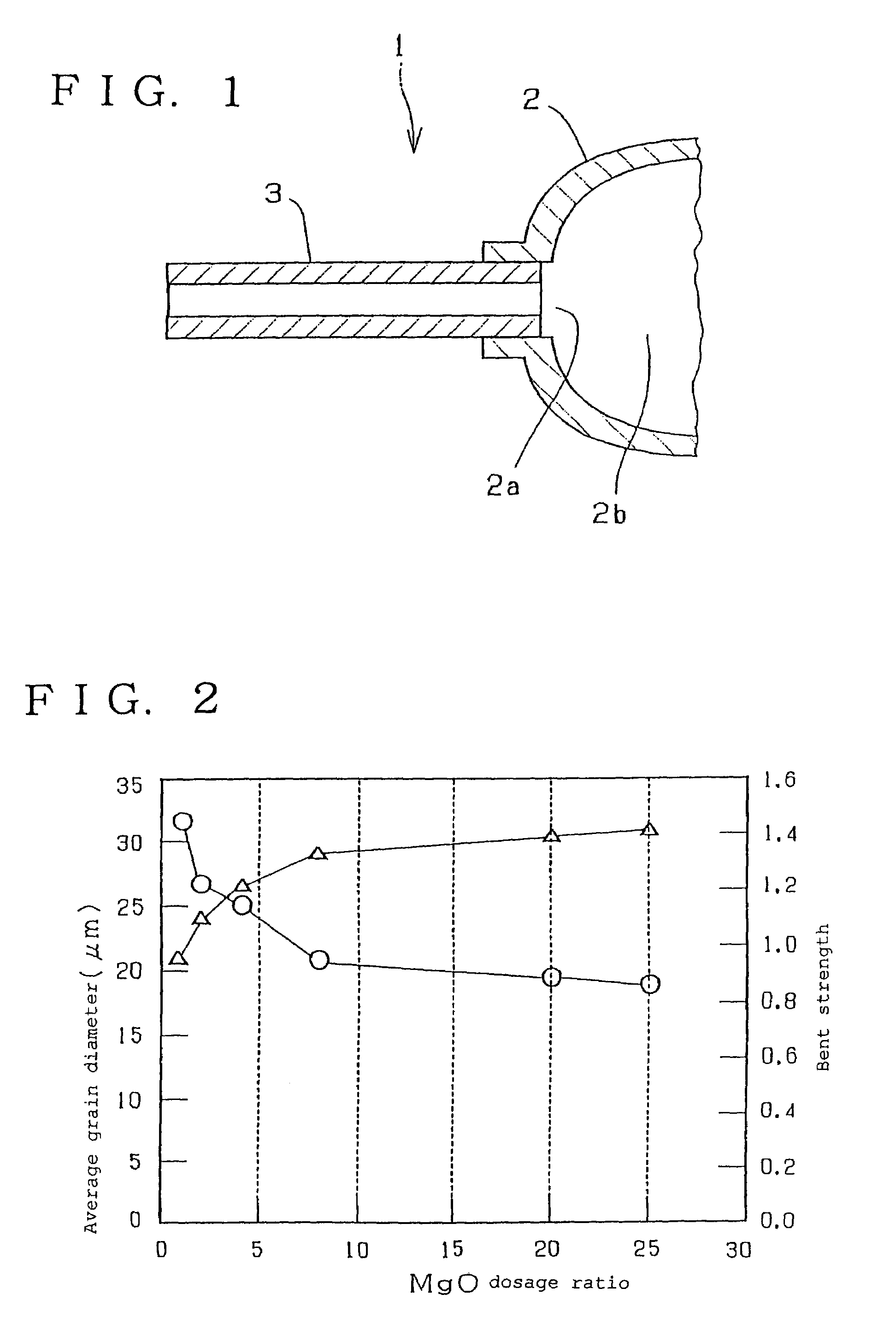
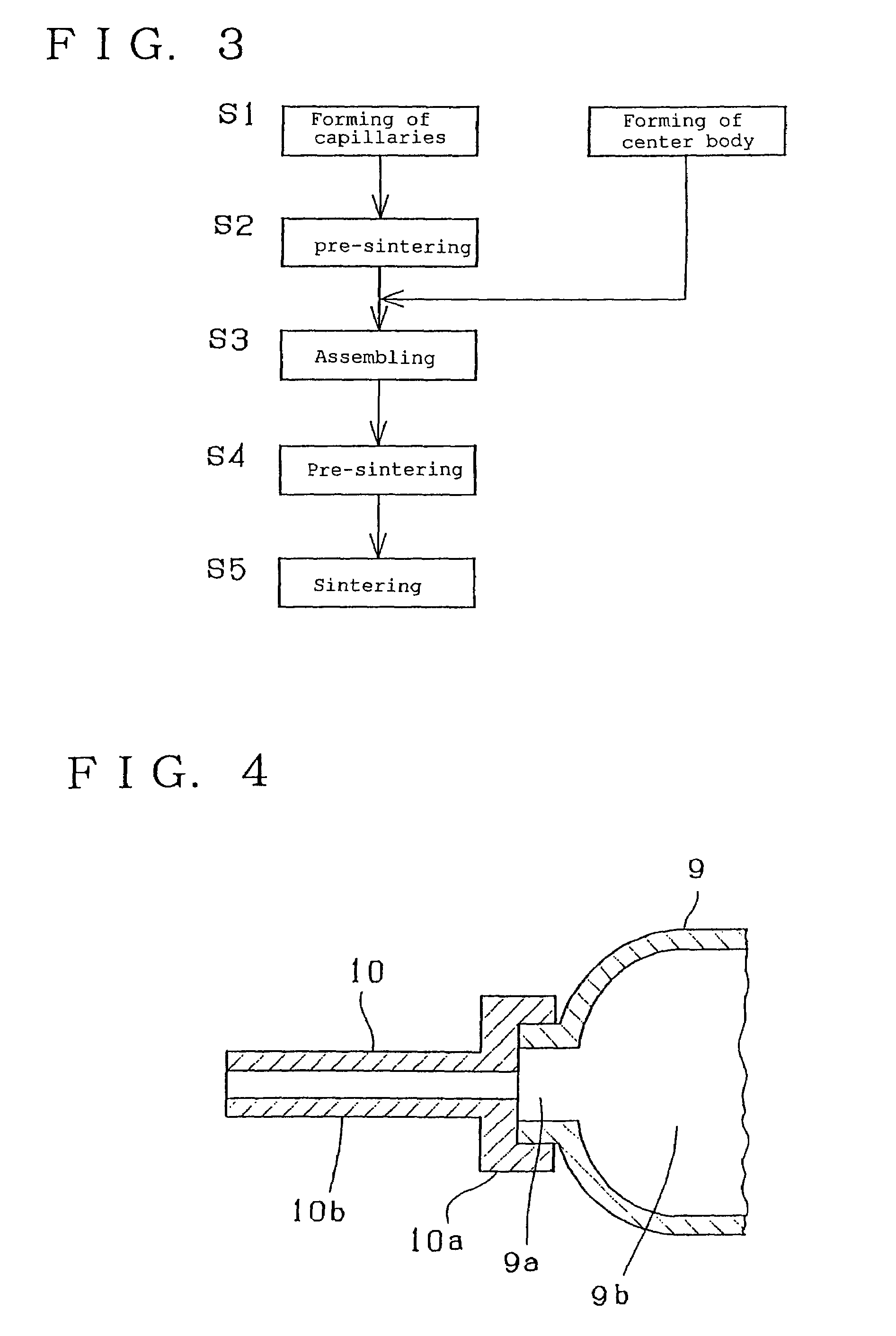
[0025]FIG. 4 is an explanatory cross sectional view of an electrode section showing the present invention. A central body 9 has an opening 9a provided at each of both, left and right (not shown), ends of a discharge space 9b thereof. Each of the openings 9a of the body 9 is closed off with a capillary 10 in which an electrode material (not shown) is inserted and secured by sealing. The capillary 10 comprises a cover portion 10a for closing the opening 9a of the body 9 and a capillary portion 10b extending outwardly and vertically from the center of the cover portion 10a.

[0026]A method of fabricating the second embodiment comprises the steps of forming the central body 9 and the capillary 10 of an alumina material or an alumina-based ceramic material and after pre-sintering, sintering the central body 9 at 1850° C. The capillary 10 after being formed is pre-baked at 1200° C. to 1400° C. Then, both are joined to each other and fired at 1700° C. The cover portion 10a is inserted into ...

third embodiment

[0028]FIG. 5 illustrates the present invention. A central body 5 of a cylindrical shape has two openings provided in both ends thereof, each the opening closed off with a ring-like plug 6. A capillary 7 is inserted into the center hole of the opening. A tubular member 8 is fitted onto the capillary 7, thus forming a double-capillary structure.

[0029]The body 5, the plug 6, and the capillary 7 are assembled and joined by a conventional sintering method, such as a shrink-fit method by sintering at 1850° C., which is based on a difference in the shrinkage. After the sintering step, the tubular member 8 is fit onto the capillary 7 and subjected to a re-sintering process. For example, the tubular member 8 is fired at 1200° C., fit onto the capillary 7, and fired again at 1700° C. to join with the capillary 7 in a shrink-fit manner.

[0030]This can increase the physical strength of the capillary, hence permitting a conventional arrangement of the discharge lamp to be increased in the physica...


PUM


Abstract

A discharge vessel or chamber for a high-intensity discharge lamp is provided, including a central body having a discharge space provided therein, two capillaries closing off respective end openings of the central body and an electrode positioned within each respective one of the capillaries. The central body and the capillaries comprise an alumina material or an alumina-based ceramic material. An average diameter of alumina grains in the central body is greater than an average diameter of alumina grains in the capillaries, and the average diameter of alumina grains in the capillaries is in a range of 10 μm to 25 μm.

Description

BACKGROUND OF THE INVENTION[0001]1. Field of the Invention[0002]The present invention relates to a discharge vessel or chamber for a high-intensity discharge lamp and particularly, to a discharge vessel or chamber having a capillary at each end thereof for holding an electrode and a method of fabricating the same.[0003]2. Description of Related Art[0004]Ceramic discharge vessels or chambers for high-intensity discharge lamps are generally classified as either an integral type where the central body defining a discharge space and a capillary for holding an electrode are integrally formed with each other, or an assembly type, wherein the body and the capillary are separately fabricated as two different components and assembled together. In either type, as shown in the explanatory cross sectional view of FIG. 6, an electrode fabricated by an electrode material 12 with a discharge electrode 14 made of tungsten or the like joining to the distal end of a current conductor 13 made of niobi...

Claims


Application Information

Patent Timeline
Patent Type & Authority Patents(United States)
IPC IPC(8): C04B35/111H01J9/24H01J9/26H01J61/30H01J61/36
CPCH01J9/266H01J61/302H01J61/361C04B2235/6582C04B2235/786C04B2235/94
Inventor MIYAZAWA, SUGIOASAI, MICHIO
Owner NGK INSULATORS LTD
Why Eureka
Try Eureka