
Engine start control device, engine start control method and recording medium having program recorded thereon for implementing engine start control method

Inactive Publication Date: 2005-11-29
TOYOTA JIDOSHA KK
View PDF14 Cites 6 Cited by
  • Summary
  • Abstract
  • Description
  • Claims
  • Application Information

AI Technical Summary

Benefits of technology

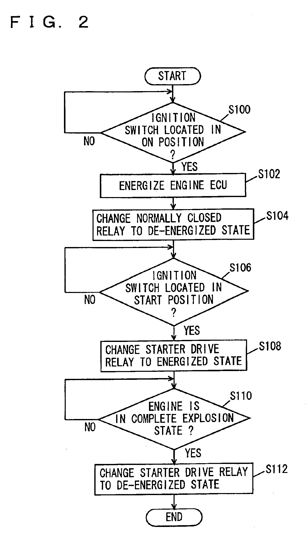
[0010]The motor which starts the engine as well as the control circuit are supplied with electric power from a power source (battery) installed in the vehicle. When the voltage supplied to the control circuit is equal to or higher than a predetermined voltage, the control circuit normally operates. When the engine is started, the motor consumes large electric power so that the voltage supplied to the control circuit temporarily decreases. At this time, the control circuit temporarily becomes inoperative. Upon satisfaction of a predetermined condition, for example, upon start of supply of the electric power from the power source, the control circuit energizes the exciting coil of the normally closed relay to establish the de-energized state between the engine starter switch and the motor. In this situation, the control circuit controls the motor based on a predetermined start condition. When a start instruction is output from the control circuit to the motor, power is supplied from the power source to the motor, which could result in a decrease of the voltage supplied to the control circuit. In this case, the energization to the exciting coil is stopped so that the energized state is established between the engine starter switch and the motor. At this time, as the energized state is established between the engine starter switch and the motor, the motor is kept supplied with electric power even if the control circuit does not normally operate. When the voltage is thereafter supplied to the control circuit as before, the exciting coil of the normally closed relay is energized. Then, the control circuit controls the motor based on the start condition and, the starting operation is completed upon a complete explosion of the engine. Moreover, even if the control circuit becomes completely inoperative, the exciting coil is de-energized and the energized state is established between the engine starter switch and the motor. Thus, the engine can be started, without the control circuit, by switching between supply and stop of electric power to the motor by the engine starter switch. In this way, the engine start control device can be provided at a low cost that is capable of starting the engine even when the computer of the engine start system is inoperative.
[0012]The control circuit and the motor are supplied with electric power from the power source installed in the vehicle. When the voltage supplied from the power source drops below a voltage which ensures the operation, the control circuit enters the inoperative state. The inoperative state of the control circuit causes energization to the exciting coil to stop so that the energized state is established between the engine starter switch and the motor. Accordingly, the engine starter switch can make a switch between supply and stop of electric power to the motor and thereby start the engine.
[0016]The engine starter switch is a switch which has a momentary-on contact and the contact is closed so long as the driver applies force. When the control circuit enters the inoperative state, energization to the exciting coil is stopped so that the energized state is established between the engine starter switch and the motor. In this case, the driver turns on the momentary-on contact so as to start supply of electric power to the motor. Knowing start of the engine from the engine sound and vibration, the driver lessen the force to turn off the momentary-on contact and thereby stop supply of electric power to the motor. In this way, the engine can normally be started.
[0018]Through the incorporation of the normally closed relay in the control circuit, the whole size of the control circuit can be reduced.
[0020]In the step of exercising control to energize the exciting coil of the normally closed relay, upon satisfaction of a predetermined condition, for example, upon start of supply of the electric power from the power source, the exciting coil of the normally closed relay is energized to establish the de-energized state between the engine starter switch and the motor. In this situation, the control circuit controls the motor based on a predetermined start condition. When a start instruction is output from the control circuit to the motor, power is supplied from the power source to the motor, which could result in a decrease of the voltage supplied to the control circuit. In this case, the energization to the exciting coil is stopped so that the energized state is established between the engine starter switch and the motor. At this time, as the energized state is established between the engine starter switch and the motor, the motor is kept supplied with electric power even if the control circuit does not normally operate. When the voltage is thereafter supplied to the control circuit as before, the exciting coil of the normally closed relay is energized. Then, the control circuit controls the motor based on the start condition and, the starting operation is completed upon a complete explosion of the engine. Moreover, even if the control circuit becomes completely inoperative, the exciting coil is de-energized and the energized state is established between the engine starter switch and the motor. Thus, the engine can be started, without the control circuit, by switching between supply and stop of electric power to the motor by the engine starter switch. In this way, the engine start control method can be provided at a low cost by which the engine can be started even when the computer of the engine start system is inoperative.
[0024]Accordingly, a program for implementing the engine start control method can be provided, at a low cost, by which the engine can be started even when the computer of an engine start system is inoperative.

Problems solved by technology

When the engine is started, the motor consumes large electric power so that the voltage supplied to the control circuit temporarily decreases.
At this time, the control circuit temporarily becomes inoperative.
When a start instruction is output from the control circuit to the motor, power is supplied from the power source to the motor, which could result in a decrease of the voltage supplied to the control circuit.

Method used


Image

  • Engine start control device, engine start control method and recording medium having program recorded thereon for implementing engine start control method
  • Engine start control device, engine start control method and recording medium having program recorded thereon for implementing engine start control method
  • Engine start control device, engine start control method and recording medium having program recorded thereon for implementing engine start control method

Examples


first embodiment

[0031

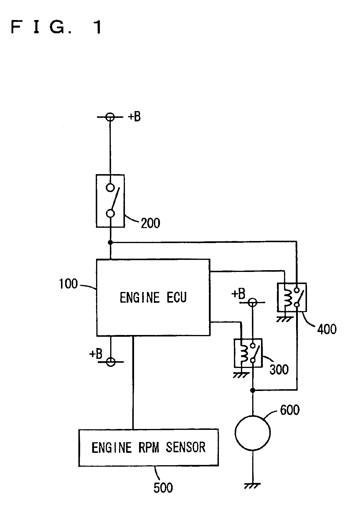
[0032]An engine start system according to a first embodiment of the present invention is now described. As shown in FIG. 1, the engine start system includes an engine ECU (Electronic Control Unit) 100 controlling start of an engine and rotation of the engine, a starter switch 200 connected to engine ECU 100, a starter drive relay 300 connected to engine ECU 100, a starter 600 connected to starter drive relay 300, and an engine rpm sensor 500 connected to engine ECU 100.

[0033]Starter switch 200 enters a switch-on state as a key is turned from the on position to the engine start position of an ignition switch. Starter switch 200 has a momentary-on contact which is turned on only when a driver holds the key in the engine start position.

[0034]Engine ECU 100 makes a determination, when the contact of starter switch 20 is turned on, as to an engine start condition stored in advance in an internal memory of engine ECU 100. If the engine is to be started, an exciting circuit of starter...

second embodiment

[0054

[0055]An engine start system according to a second embodiment of the present invention is now described. It is noted that any description which is common to the first and second embodiments and has already been given above is not repeated here.

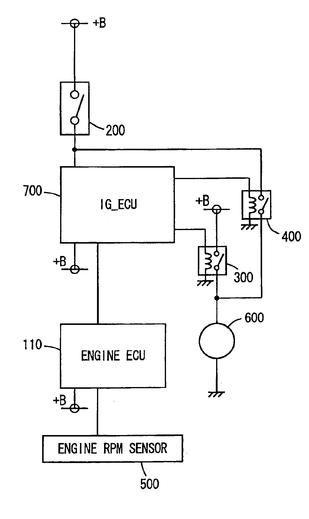
[0056]Referring to FIG. 5, the engine start system according to this embodiment includes an IG_ECU 700 in addition to the components of the engine start system of the first embodiment shown in FIG. 1. IG_ECU 700 is connected to an engine ECU110, and an engine rpm sensor 500 is connected to engine ECU 110. IG_ECU 700 and engine ECU 110 are both supplied with electric power from a battery. Further, IG_ECU 700 is connected to a starter switch 200, a starter drive relay 300 and a normally closed relay 400.

[0057]When the ignition switch is turned to the on position, IG_ECU 700 is supplied with electric power from the battery to start its operation. At this time, IG_ECU 700 energizes an exciting circuit of normally closed relay 400 so that the ...


PUM


Abstract

An engine start system includes a starter starting an engine, a starter drive relay controlling the starter and an engine ECU connected to a starter switch for controlling on / off of the starter drive relay based on a predetermined start condition. The engine start system further includes a normally closed relay connected to the starter switch, the engine ECU and the starter for establishing a de-energized state between the starter switch and the starter upon energization from the engine ECU to an exciting coil and establishing an energized state between the starter switch and the starter upon de-energization of the exciting coil. The engine ECU includes a circuit energizing the exciting coil of the normally closed relay upon turn-on of the engine ECU.

Description

TECHNICAL FIELD[0001]The present invention relates to a start control device for an engine of a vehicle. More particularly, the present invention relates to a start control device capable of starting the engine even if a computer controlling the start of the engine is inoperative.BACKGROUND ART[0002]An engine of a vehicle is usually started by operation of an ignition switch. The ignition switch is operated by an ignition key inserted into a key slot and then turned to a predetermined position. The ignition switch has an off (OFF) position for insertion and removal of the ignition key, an accessory (ACC) position for energizing electrical accessories, for example, car audio system and the like, an on (IG-ON) position for energizing an ignition system of the engine, and an engine start (ST) position for energizing a starter thereby starting the engine. The ignition key in the engine start position returns to the on position unless a driver applies force to the key to hold the key in ...

Claims


Application Information

Patent Timeline
IPC IPC(8): F02D45/00F02N15/00F02N11/08F02N11/10
CPCF02N11/08F02N11/10F02D2400/14F02N2250/02
Inventor KITAGAWA, TAKUMI
Owner TOYOTA JIDOSHA KK
Learn More