
Dual-zero sight for a firearm

a single sight, zero-zero technology, applied in the field of single-sighting devices, can solve the problems of difficult or impractical carrying several firearms in the field, and the problem of unable to achieve the effect of zeroing in or “sighting in” targets with different loads using a single sigh

Active Publication Date: 2005-11-29
WOODBURY MARTIN
View PDF31 Cites 22 Cited by
  • Summary
  • Abstract
  • Description
  • Claims
  • Application Information

AI Technical Summary

Benefits of technology

[0014]Windage adjustment for the multiple-zero sighting device may be accomplished by moving the pivot arm transversely relative to the longitudinal axis of the firearm and / or may be accomplished by moving the sights transversely relative to the pivot arm. Elevation adjustment may be accomplished by pivoting the pivot arm to varying angles relative to the firearm and / or by moving the sights longitudinally on the pivot arm. Preferably, these sight-alignment calibrations are performed once, prior to entering the field, thereby eliminating the need for complex in-the-field adjustments when switching between ammunition types and rear sight components.

Problems solved by technology

For hunters, sportsmen, law enforcement personnel and other gun users, it is difficult or impractical to carry several firearms in the field.
Due to the substantially different ballistic characteristics of these loads, “zeroing-in” or “sighting-in” targets with these different loads using a single sight can be problematic.

Method used


Image

  • Dual-zero sight for a firearm
  • Dual-zero sight for a firearm
  • Dual-zero sight for a firearm

Examples


Embodiment Construction

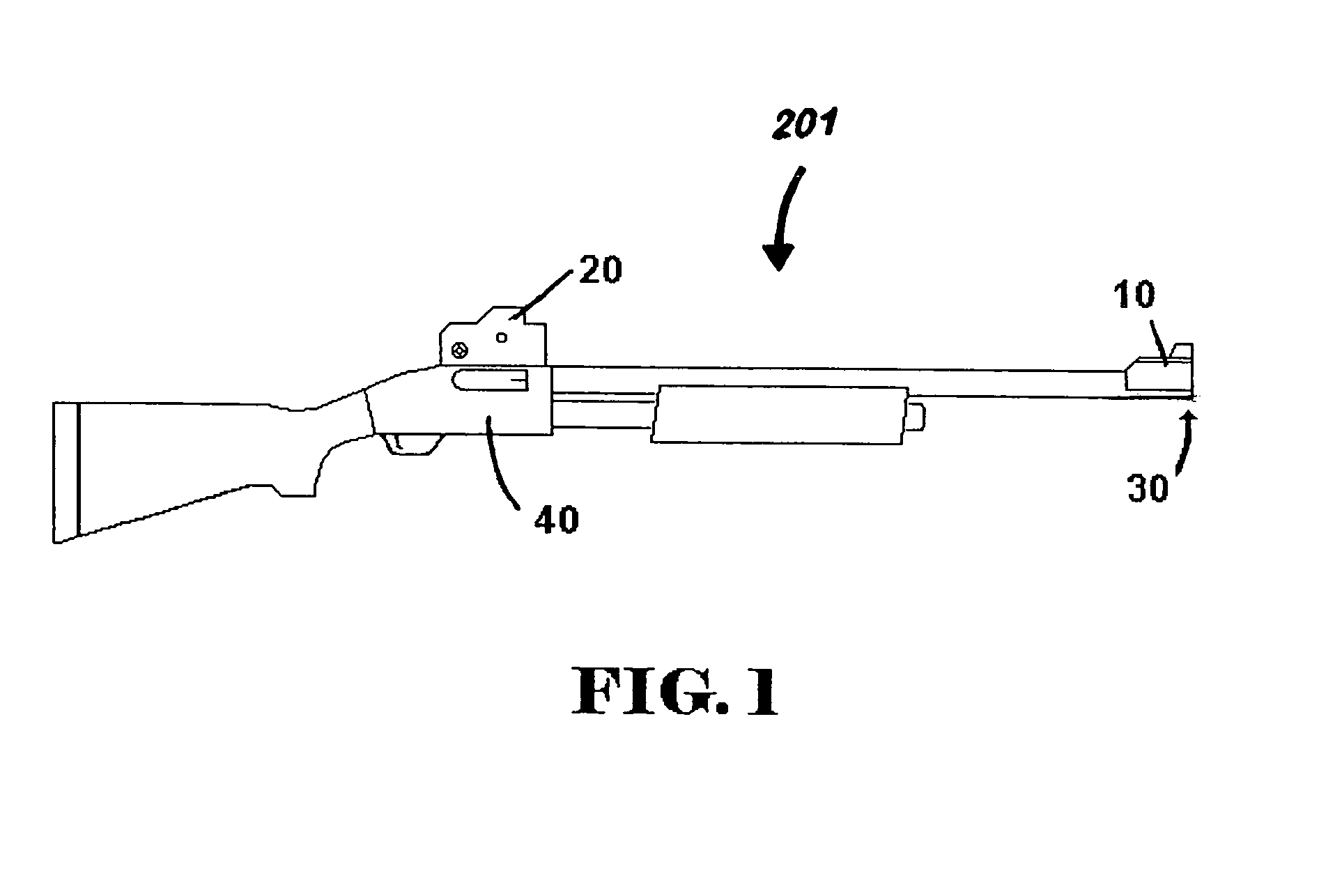
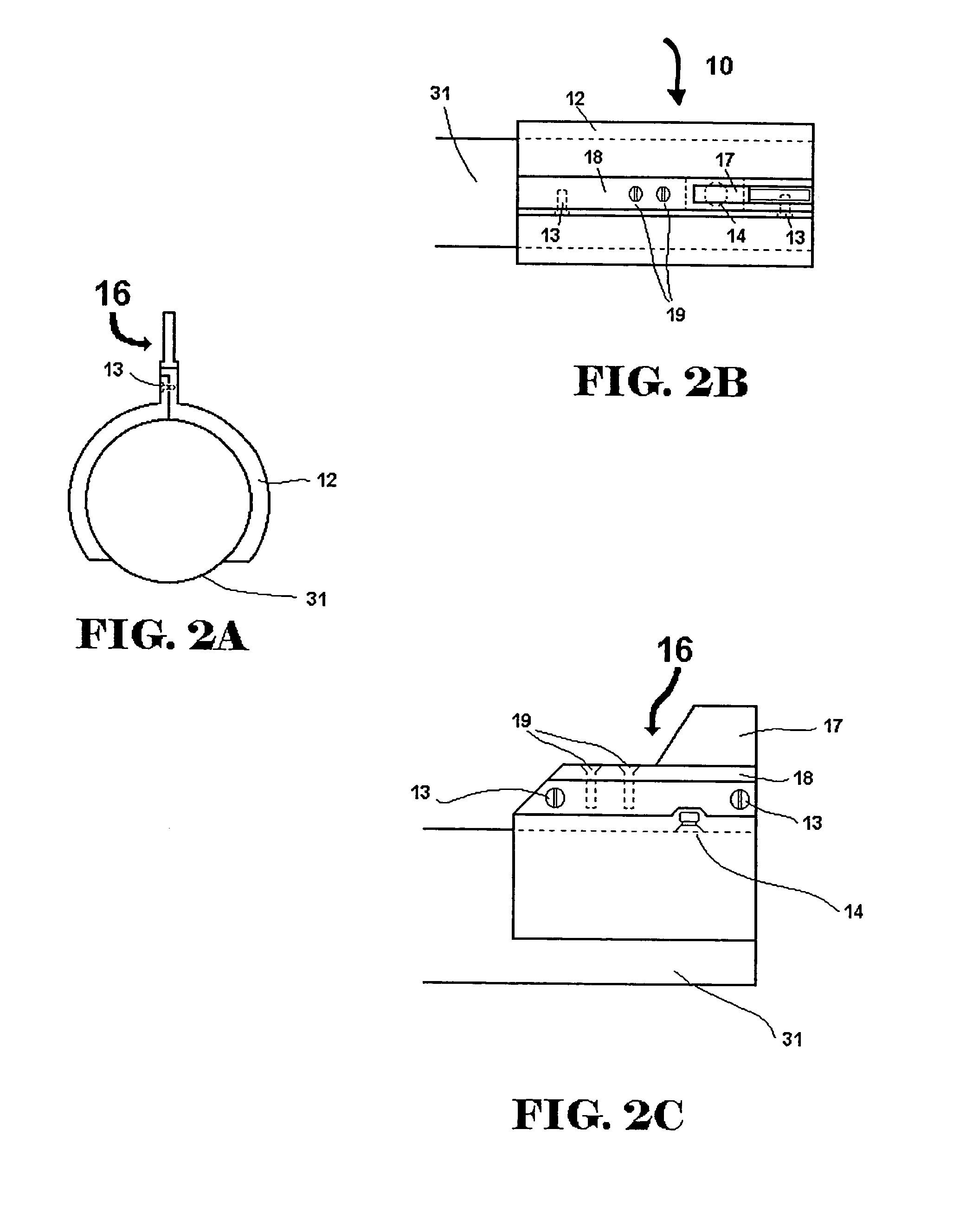
[0041]Referring to FIGS. 1–6, there are shown some, but not the only, embodiments of a front and rear sight system for a firearm, wherein the rear sight features a pivotal L-shaped frame having two separate sights. One sight is located on each arm of the L-shaped frame. The sights are flipped into operable position by pivoting the L-shaped frame. Each sight has separate windage and elevation controls.

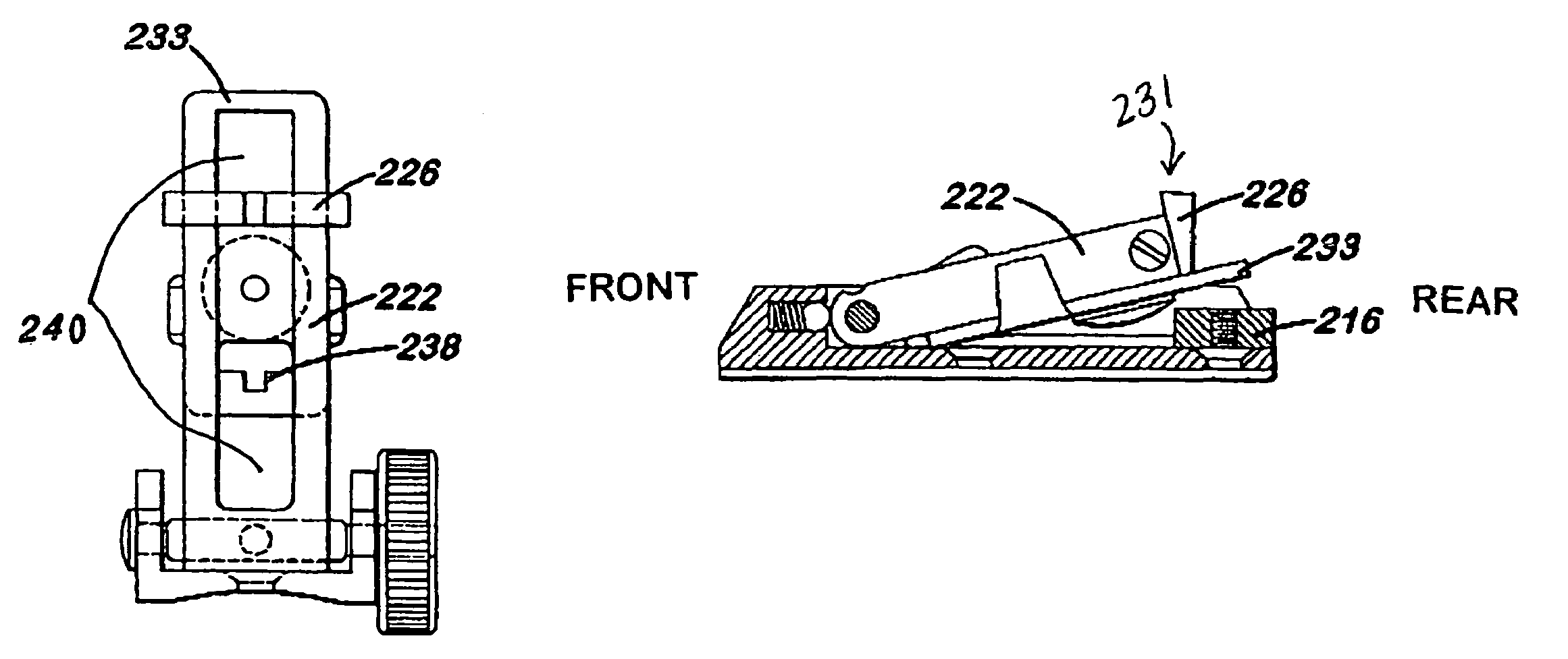
[0042]Referring to FIGS. 7–17, there is shown one, but not the only, embodiment of a rear sight unit, wherein the rear sight features two sights on a single pivotal arm. Preferably, the two sights are located on opposites sides of the pivot arm. The sight on the front side of the pivot arm is used when the arm is pivoted to the upright position. The sight on the rear side of the pivot arm is used when the arm is pivoted down toward the firearm.

FIGS. 1–6

[0043]Referring to FIGS. 1–6, a lesser preferred, but not the only, embodiment of an adjustable sighting device for buckshot and slug am...


PUM


Abstract

A sighting system for a firearm includes a rear sight unit having a plurality of separate sight elements adaptable for “zeroing” the same gun with different ammunition. The multiple-zero sight unit comprises windage and elevation adjustments for each sight element, so that multiple ammunition types having different trajectories may be fired accurately from a single firearm after zeroing-in one of the plurality of sight elements for each of the different ammunition types. Preferably, the separate sight elements may be connected to each other or to a common pivot arm or movable bracket so that moving one sight element into the sight path automatically removes the other from the line of vision. Elevation adjustments may be done in various ways, for example, by sliding sight elements out along an arm or bracket, or by changing an angle of the arm or bracket relative to the firearm. The preferred sighting system also includes an adjustable front sight unit, which can be raised or lowered in elevation, by sliding a fin or blade up or down or by adding or removing an extension member. Adding the extension member may provide a gross adjustment of the front end of the firearm by significantly lowering the barrel position for a given line of sight between the user's eye, the selected rear sight, and the front sight.

Description

[0001]This application claims priority of Provisional Application Ser. No. 60 / 445,173, filed Feb. 3, 2003, entitled “Dual-Zero Sight”, which is hereby incorporated by reference.BACKGROUND OF THE INVENTION[0002]1. Field of the Invention[0003]This invention relates, in general, to gun sights for shotguns and other firearms. More specifically, this invention relates to a single, adjustable sighting device that may be used for sighting-in a plurality of ammunition, for example, long range and close range ammunition.[0004]2. Related Art[0005]For hunters, sportsmen, law enforcement personnel and other gun users, it is difficult or impractical to carry several firearms in the field. However, the type of ammunition used is often changed in response to the demands of different situations, for example, the change from large to small game. Consequently, a number of smoothbore firearms, and their ammunition, have been modified to improve their effectiveness over a range of shooting tasks. One s...

Claims


Application Information

Patent Timeline
IPC IPC(8): F41G1/033F41G1/10F41G1/42
CPCF41G1/033F41G1/10F41G1/42
Inventor WOODBURY, MARTIN
Owner WOODBURY MARTIN
Learn More