Video or information processing method and processing apparatus, and monitoring method and monitoring apparatus using the same

Inactive Publication Date: 2005-11-15
HITACHI LTD
View PDF45 Cites 217 Cited by
  • Summary
  • Abstract
  • Description
  • Claims
  • Application Information

AI Technical Summary

Benefits of technology

[0062]An object in a video picture on a screen is directly designated, and an operation instruction is sent to the designated object. While observing an actually imaged picture of the object, an operator performs an operation instruction. When the object is visually moved in response to the operation instruction, this movement is directly reflected on the picture of the camera. Thus, the operator can execute the remote operation with having such a feeling that he is actually tasking in a field by directly performing operation with respect to the actually imaged picture. As a consequence, the operator can intuitively grasp an object to be operated and also a result of the operation, so that an erroneous operation can be reduced.
[0065]Based on the object within the image designated on the screen, information is represented. As a consequence, the information related to the object within the image can be referred by only designating the object. While referring to an image and other information at the same time, it is easily possible to make a decision on conditions.
[0066]Either a text, or a pattern is inputted as a search key, and then a picture is displayed in which an object matched to the inputted search key is being displayed. The text is inputted by way of a character inputting device such as a keyboard, a speech recognition apparatus, and a handwritten character recognition apparatus. Alternatively, the pattern may be inputted by employing PD, or data which has been formed by other method is inputted. Also, the text or the pattern located in the picture may be designated as the search key. In case that the image to be search corresponds to the image from the camera, based on the search key, the camera is selected, and furthermore the direction of the camera and also the lens thereof are controlled, so that the search key can be imaged. It is also possible to clearly indicate where a portion matched to the search key is located with the picture by properly synthesizing the graphics with the image in which the object adapted to the search key is being represented. As described above, the picture is represented based on the search key, and the operator merely represents a desirable object to be seen with a language or a pattern, so that such a desirable image can be obtained for an observation purpose.

Problems solved by technology

Since it is difficult to propagate the feeling of attendance in an actual place by way of the remote controls with employment of the keys, buttons and levers provided on the operation panel, and the menu and icon displayed on the monitor screen, the actual object to be operated and the operation result can be hardly and intuitively grasped.
The operator must directly switches the cameras and also directly perform the remote control operation, and cannot simply select such a camera capable of imaging a desirable scene in case that a large number of cameras are employed to monitor the scene.
A cumbersome task is required to observe the desirable scene by operating the camera positioned at a remote place.(3).
Accordingly, the problems are such that the resultant apparatus becomes bulky, and the mutual reference between the video image and the other data becomes difficult.(4).
Although a video image of a camera owns a great effect to propagate the feeling of attendance, since this picture has a large quantity of information and also is not abstracted, there is a drawback that an operator can hardly and intuitively grasp a structure within the camera's picture.
However, these graphic representations are separated from the actual object and the actual matter, and therefore there is a risk that an operator cannot readily imagine the relationship among the graphic representations and the actual matter / object.(5).
As a consequence, a comprehensive judgement of the conditions can be made difficult.
However, an image related to the picture and control information cannot be referred by designating a content (appliance and the like being displayed) represented in the video image.
However, the designation of the appliance cannot be directly performed on the screen.

Method used


Image

  • Video or information processing method and processing apparatus, and monitoring method and monitoring apparatus using the same
  • Video or information processing method and processing apparatus, and monitoring method and monitoring apparatus using the same
  • Video or information processing method and processing apparatus, and monitoring method and monitoring apparatus using the same

Examples


second embodiment

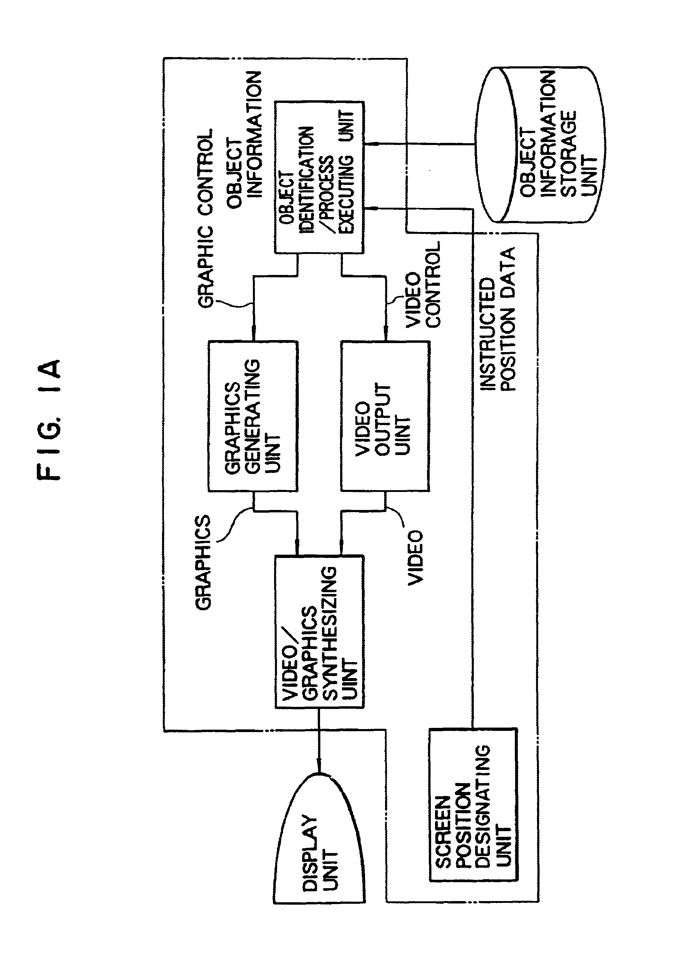
[0133]Also, the portion surrounded by the dot and dash line in FIG. 1A establishes a relationship between the control data and the sound or video data based upon the above-described relating information in the

first embodiment

[0134]Referring now to drawings, embodiments of the present invention will be explained. First, a plant operation monitoring system corresponding to one embodiment (first embodiment) of the present invention, to which the video or information processing method and apparatus of the present invention have been applied with employment of FIGS. 2 to 28.

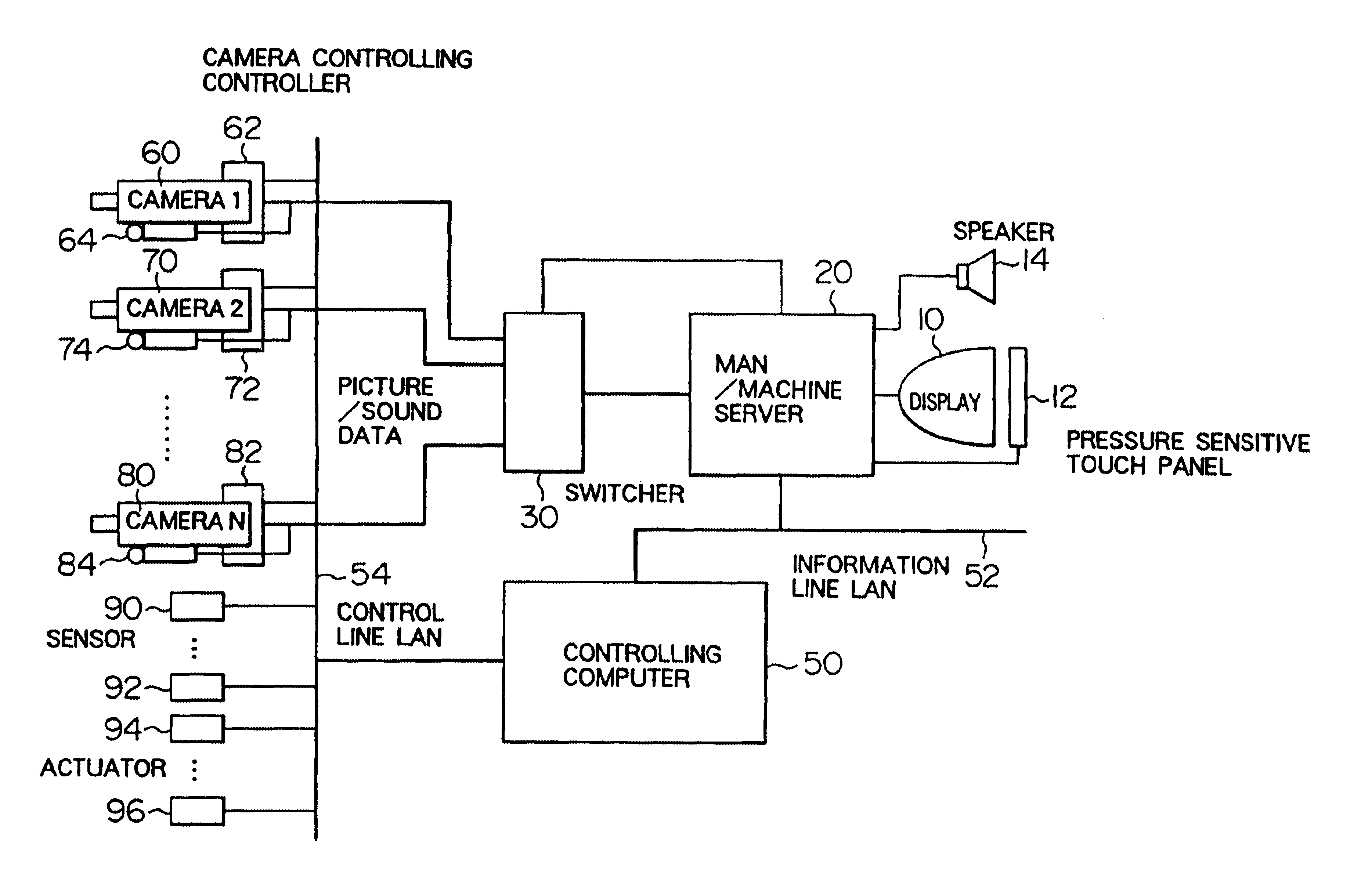
[0135]An overall arrangement of this embodiment is explained with reference to FIG. 2. In FIG. 2, reference numeral 10 denotes a display functioning as a display means for displaying graphics and video; reference numeral 12 shows a pressure sensitive touch panel functioning as an input means mounted on an overall surface of the display 10; reference numeral 14 is a speaker for outputting a sound; reference numeral 20 indicates a man-machine server used to monitor and operate the plant by an operator; and reference numeral 30 is a switcher for selecting one video input and one sound input from a plurality of video inputs and also a plurali...

embodiment 1

[0355]A reading method of this example will now be described with reference to FIG. 41. An algorithm shown in FIG. 41 has such different points, as compared with the algorithm of FIG. 39, that a time instant “t” denoted by the time cursor is detected at a process 3301, and also a judgement of a process 3302 is made as to whether or not the time instant “t” has been previously buffered within the work station 2103. At the process 3301, the coordinate value of the input signal by the pointing device such as the touch panel and the like is processed by the CPU 2201 in the work station 2103, the time cursor 2503 is again drawn on this coordinate system and also the time instant denoted by the time cursor 2503 is calculated from the coordinate value. If the data at the time instant “t” is not buffered within the work station 2103, the sequential steps 3105 and 3106 defined in the preferred embodiment 1 are carried out, and then the data, video and sound are displayed at the sequential st...


PUM


Abstract

In a remote operation monitoring system and the like, it is a video processing apparatus capable of intuitively grasping an object operated by an operator and an operation result. The video processing apparatus includes a unit (310, 320, 2104, 2202) for storing information about at least one object displayed on a screen of a display unit; a unit (12, 2105) for designating information about the object; a unit (300, 2201) for searching the store unit based upon the designated information, and for obtaining information within the store unit corresponding to the designated information; and also a unit (20, 2103) for performing a process related to the object based on the obtained information. An operator can readily grasp an object to be operated and a result.

Description

CROSS-REFERENCE TO RELATED APPLICATIONS[0001]This application is a Rule 53(b) continuation of U.S. Ser. No. 08 / 328,566 filed 24 Oct. 1994, now U.S. Pat. No. 6,335,722, which is a Rule 62 Continuation of U.S. Ser. No. 07 / 960,442 filed 8 Dec. 1992, now abandoned, which is a 371 of PCT / JP92 / 00434 filed Apr. 8, 1992.TECHNICAL FIELD[0002]The present invention relates to a man-machine interface with utilizing sound data or video data (simply referred to a “man-machine interface”), and in particular, to a video or information processing method and a processing apparatus for performing a process for an object with employment of sound data or video data of this object, and also to an object monitoring method and a monitoring method with utilizing the processing method / apparatus.BACKGROUND ART[0003]To safely operate a large-scaled plant system such as a nuclear (atomic) power plant, an operation monitoring system including a proper man-machine interface is necessarily required. A plant is ope...

Claims


Application Information

Patent Timeline
IPC IPC(8): G05B23/02G06F3/033G06F3/0481
CPCG05B23/0216G05B23/0267G06F3/0481H04N7/18
Inventor TANI, MASAYUKIYAMAASHI, KIMIYATANIKOSHI, KOICHIROFUTAKAWA, MASAYASUTANIFUJI, SHINYANISHIKAWA, ATSUHIKOHIROTA, ATSUHIKO
Owner HITACHI LTD
Why Eureka
Try Eureka