Pen projection display

a projection display and pen technology, applied in the field of projection displays, can solve the problems of limiting the size of conventional computers, and achieve the effect of convenient reading

Inactive Publication Date: 2005-11-15
MICROSOFT TECH LICENSING LLC
View PDF13 Cites 25 Cited by
  • Summary
  • Abstract
  • Description
  • Claims
  • Application Information

AI Technical Summary

Problems solved by technology

Accordingly, while the processing and memory components of a computer can be made very small, further reduction in the size of conventional computers is practically limited by the need to have a visible display monitor.

Method used


Image

  • Pen projection display
  • Pen projection display
  • Pen projection display

Examples


Embodiment Construction

Overview

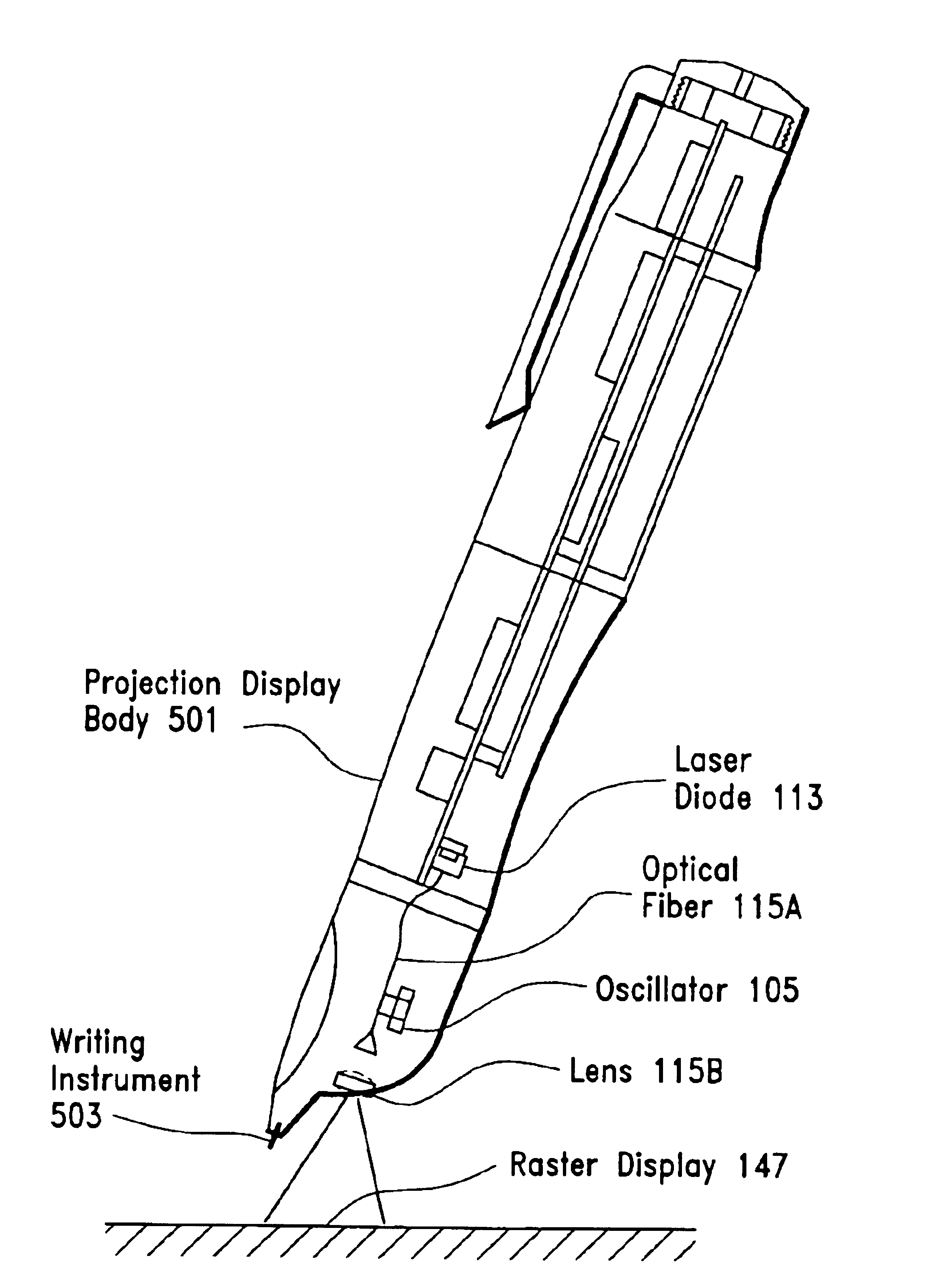
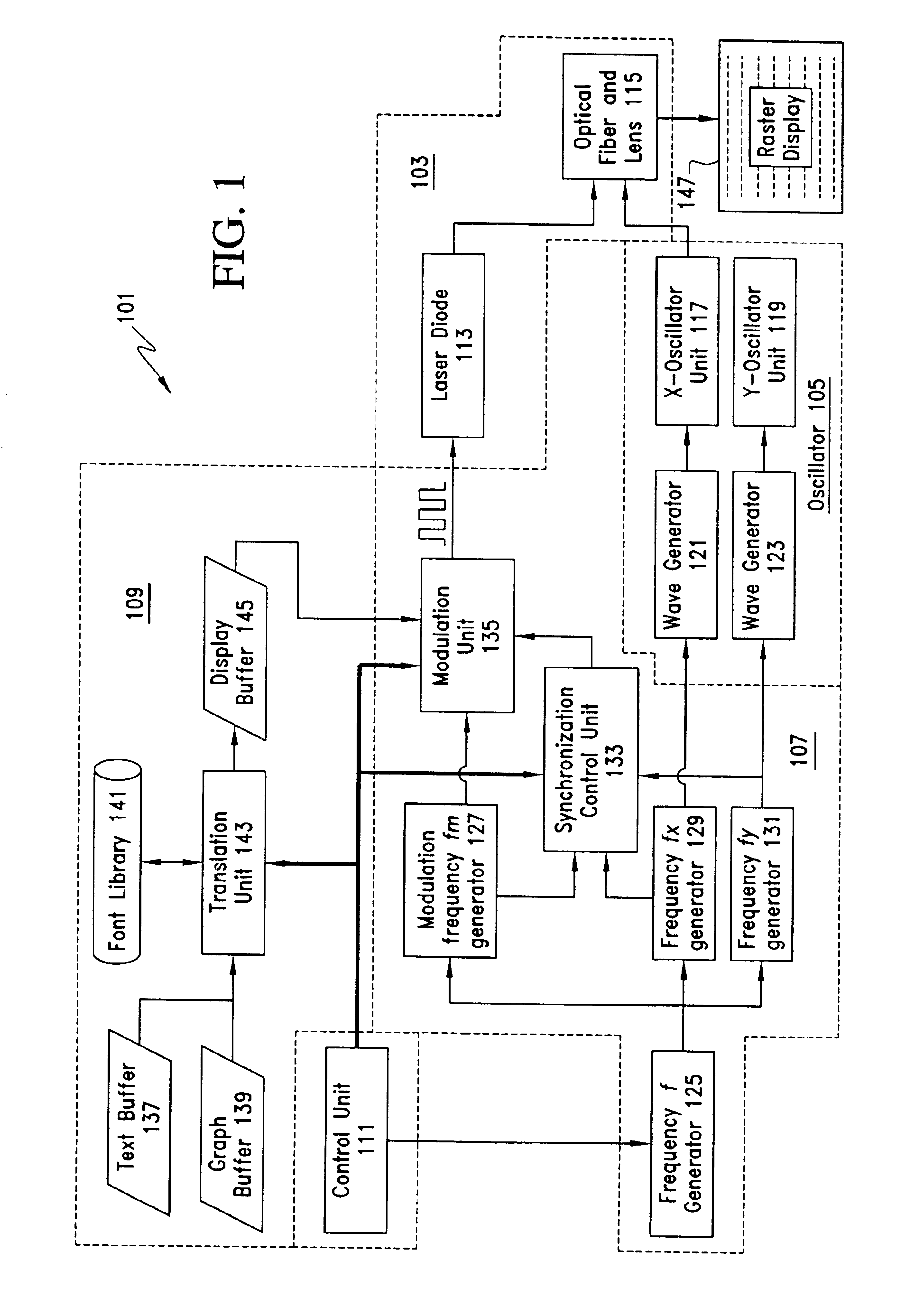
[0013]FIG. 1 illustrates a projection display 101 according to one embodiment of the invention. As seen in this figure, the projection display 101 includes a light projector unit 103 for generating and projecting light, an oscillator unit 105 for oscillating light projected from the light projector unit 103, and a frequency generation and modulation unit 107. The projection display 101 also includes an image data input unit 109 and a control unit 111. As will be explained in detail below, the frequency generation and modulation unit 107 drives the oscillator unit 105 and modulates the light projected by the light projector unit 103. In turn, the oscillator unit 105 oscillates the light projected by the light projector unit 103 in two dimensions.

[0014]More particularly, the oscillator unit 105 oscillates the light produced by the light projector unit 103 so that the projected light scans an incident surface in a raster pattern. At the same time, the frequency generation and m...


PUM


Abstract

The projection display includes a light projector unit for generating and projecting light, an oscillator unit for oscillating light projected from the light projector unit, and a frequency generation and modulation unit. The frequency generation and modulation unit drives the oscillator unit and modulates the light projected by the light projector unit. In turn, the oscillator unit oscillates the light projected by the light projector unit in two dimensions, so that the projected light scans an incident surface in a raster pattern. At the same time, the frequency generation and modulation unit modulates the light produced by the light projector unit in synchronization with the scanning process and image data supplied so that the projected light produces images corresponding to the image data over a scanned area.

Description

[0001]This is a continuation of Application Ser. No. 10 / 284,470 filed Oct. 31, 2002.FIELD OF THE INVENTION[0002]The present invention relates to a projection display. The invention has particular application to a projection display that can be incorporated into a hand-held writing device, such as an ink pen or computer stylus.BACKGROUND OF THE INVENTION[0003]Computers have become ubiquitous in our society, and are used in every facet of daily life. While modern computers can provide information to a user audibly, the primary mode of conveying information for most computers is visual. That is, most computers will display information to a user visually on a monitor, such as a cathode ray tube monitor, a liquid crystal display monitor, or a plasma monitor. Accordingly, while the processing and memory components of a computer can be made very small, further reduction in the size of conventional computers is practically limited by the need to have a visible display monitor. Accordingly, ...

Claims


Application Information

Patent Timeline
Patent Type & Authority Patents(United States)
IPC IPC(8): H04N9/31G02B26/10B43K29/00B43K29/10G06F3/033G09G3/02G09G3/20H04N3/02
CPCB43K29/00B43K29/10H04N9/3129H04N9/14G06F3/0354G06F3/03
Inventor WANG, JIANZHANG, CHUNHUI
Owner MICROSOFT TECH LICENSING LLC
Why Eureka
Try Eureka